Instructions For Bluebeam Resources
From DelDOT CADD Wiki
Introduction
This document will guide the trainee through the setup and utilization of the DelDOT CADD resources available in Bluebeam Revu. Please note that certain parts of this training requires a licensed copy of Bluebeam.
Click to request a licensed copy
These resources are still under construction internally. For those external to the Department that would like access to the resources, please contact DOT_CADDSupport@delaware.gov.
Revision Summary
This section provides a summary of significant revisions and additions to this WikiPage. To view the full history, select View History in the top right corner of the MediaWiki page. This document is intended to be an ongoing process that is frequently updated.
- 8/10/2021: Initial Release
Accessing and Using Bluebeam Resources
1. Initial Setup
1.1 Load the DelDOT Plan Production Profile.
The DelDOT Plan Production Profile will load the appropriate Toolbars, Tool Chests, Linestyles, Hatch Patterns, and Panels. When these resources are no longer needed, you can switch back to the standard DelDOT Profile.
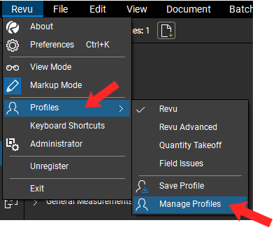
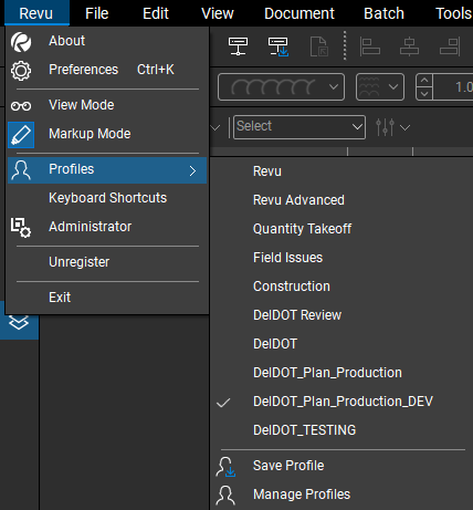
1.1.1. Navigate to the top left corner and click on Revu > Profiles > Manage Profiles.
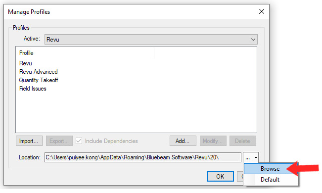
1.1.2. In the Manage Profiles dialog, select Browse from the dropdown on the bottom right.
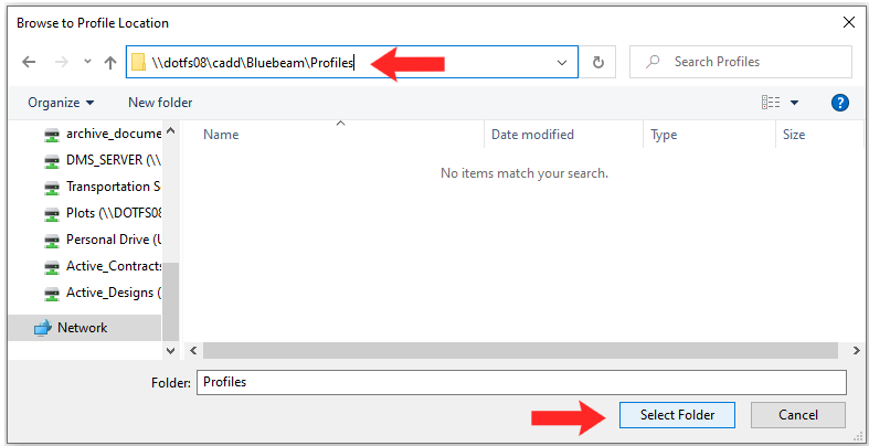
1.1.3. In the Browse to Profile Location dialog, paste the following into the address bar at the top: \\dotfs08\cadd\Bluebeam\Profiles and click Select Folder.
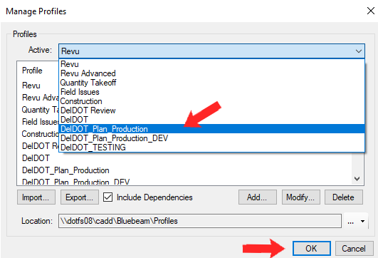
1.1.4. In the Manage Profiles window, change the active profile to DelDOT_Plan_Production and click the OK button.
1.1.5. To switch profiles from now on, navigate to Revu > Profiles at the top left of the screen and select the profile you intend to utilize.
1.2 Calibrating Page Scale.
The following section will cover calibrating the Page Scale. Accurately setting the Page Scale is required for many of the resources, as well as obtaining accurate measurements and distances. ! Please note that the following section requires that you have a licensed copy of Bluebeam.
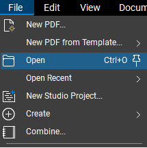
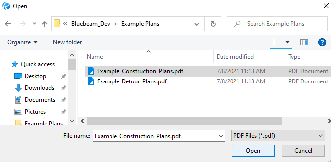
1.2.1. Go to the top left of the screen and select File > Open and find the plan you intend to calibrate from the File Open Window. Click the Open button when finished. ! Dragging a PDF directly into Bluebeam is another way to open a file.
1.2.2. Turn on your snaps by selecting the Snap to Content and Snap to Markup settings in the bottom right corner of the application.
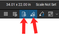
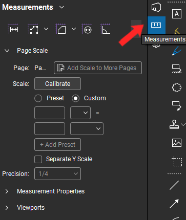
1.2.3. Navigate to the right side of your screen and click on the ruler icon to open up the Measurements panel. ! If you do not see the measurement icon, press Alt + U on your keyboard.
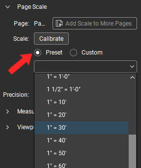
1.2.4. If your plan has a standard scale, you can select a Preset option and choose the appropriate scale from the drop down.
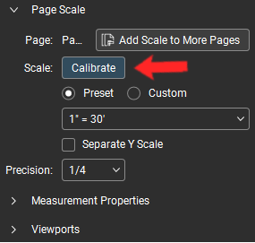
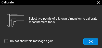
1.2.5. To manually calibrate your page, click the Calibrate button and click OK on the popup message.
1.2.6. Locate and zoom into the scale bar on your plan sheet.
1.2.7. For Vectorized plans, move your mouse to the top left corner of the Scale Bar until you see the square blue Snap icon and click to set the first Calibration point. Repeat on the end of the Scale Bar to set the second Calibration point. Holding the Shift key will ensure that the line drawn is completely straight. ! See section 2.1 for more information about snaps.
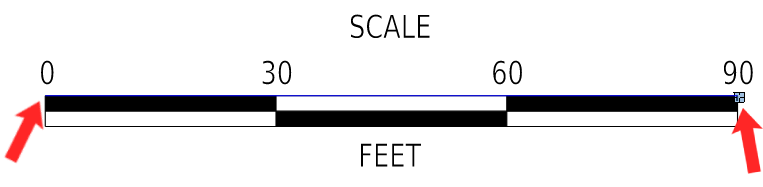
! Use the full length of the Scale Bar and try to be as accurate as possible as small inaccuracies add up quickly over short distances. For Rasterized plans, zoom into the Scale Bar and click the top left corner to set the first calibration point. Hold the Shift key and click on the top right corner of the Scale Bar to set the second Calibration point. ! Holding the Shift key ensures that the line drawn is completely straight for more accuracy.
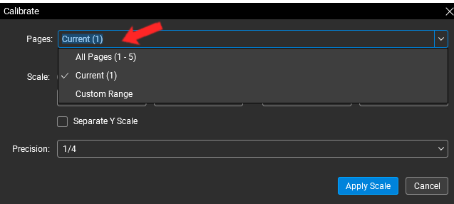
1.2.8. In the Calibrate dialog, select the appropriate option from the Pages dropdown. ! If working with a page that is to a different scale than the rest of the plan, you must go back in and manually recalibrate the scale following steps 1.2.7-1.2.11 to maintain accuracy.
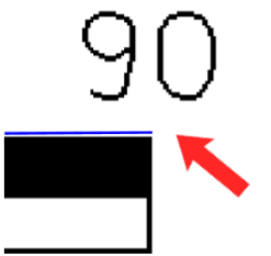
1.2.9. Do not change the first two fields. Change the third field to match the value on the rightmost side of the scale bar on your plan and select the correct unit from the dropdown.
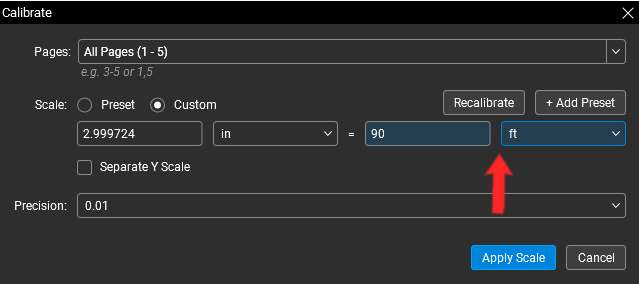
1.2.10. If you have a separate vertical scale, check “Separate Y Scale” and repeat steps 1.2.6 to 1.2.9.
1.2.11. Click Apply Scale. ! The value you input may vary from plan to plan, so be sure to do this every time you open a new plan for the most accurate results.
1.3 Accessing the Tool Chest Panel.
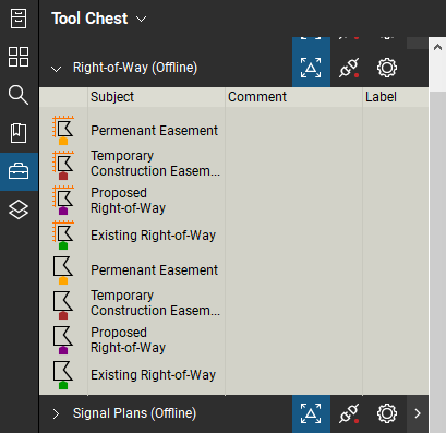
The Tool Chest panel contains various Tool Sets, which house all the available DelDOT CADD resources. By Default, the Tool Chest panel will be on the left side of your screen. ! If you do not see the toolbox icon, press Alt + X on your keyboard.
1.3.1. Expand and contract Tool Sets as necessary. ! The “disconnected” icon with the red dot inside the Tool Chest is normal! Click on the icon to sync with the tools. A lock icon should appear.
2. General Resources
2.1 Snaps.
Snaps allow users to precisely select points within plans. Snaps work on vectorized files and Bluebeam-created elements by finding exact points on the plans to "snap" to. Thus, if working in a rasterized file, there will be no options to snap to despite snaps being on as the file is pixilated. ! See section 1.3.2 for more information on turning on and off snaps.
2.1.1. When manipulating and creating items as well as calibrating page scale, a clear square icon at the point of intersection means that the markup tool is being snapped onto a point along the plan. ! When placing or dragging an item, the "snap point" is based nearest to where you clicked to drag the item.
2.1.2. No square icon at all indicates that the markup tool is not being moved onto a snappable point along the plan.
2.1.3. A blue square icon means that the resource is being snapped directly onto a keypoint along the plans, for example the end-point or midpoint of a line or arc.
2.2 Lines.
A Line is a straight cord between two vertices. A Polyline can be a Line if only two vertices are specified. An example of Line resources are crosswalks. ! See section 2.3 for more details on polylines.
2.2.1. Click once on your selected line tool from the Tool Chest.
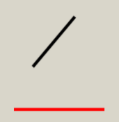
2.2.2. Click on the plan to place the first vertex. After selecting the second vertex, the line ends automatically as a line can only have two vertices.
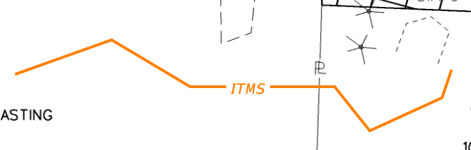
2.3 Polylines.
A Polyline is a series of straight or curved cords that connect multiple vertices. Examples of polylines are ITMS lines and utilities lines.
2.3.1. Click once on your selected polyline tool from the Tool Chest.

2.3.2. Click on the plan to place the first vertex. Continue placing vertices as necessary. To end the polyline, double-click the left mouse button or hit the Enter key. ! Unlike Microstation, a right click will get rid of the entire line rather than finishing it.
If you want to undo a vertex, pressing the Ctrl + Z keys on the keyboard will undo the last vertex you placed, allowing you to fix the line without completely restarting. ! Reference sections 4.2 and 4.3 on working with control points.
2.4 Polygons.
The Polygon tool connects a series of straight or curved cords to form a closed shape. Unlike Polylines, since Polygons are closed shapes, they can be filled. An example of a polygon is the Whiteout tool. ! See section 2.3 for more on Polylines.
2.4.1. Click once on your selected polygon tool from the Tool Chest.

2.4.2. Click on the plan sheet to create a polygon with as many vertices and sides as you’d like. To close the Polygon, click near the point of beginning, double click anywhere, or hit the Enter key.
The Ctrl + Z keys on the keyboard allow you to undo the last vertex placed.
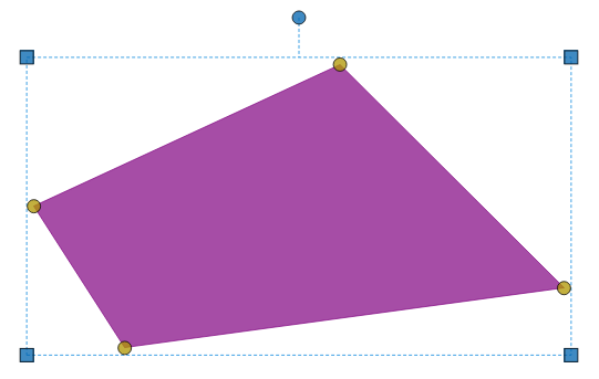
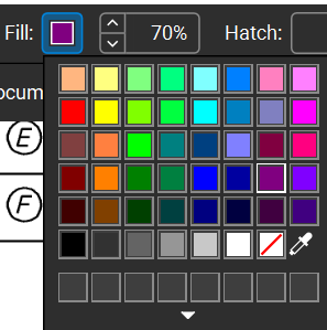
2.4.3. Polygons can be filled as necessary. To do so, navigate to the top properties bar and click on the colored square next to Fill:.
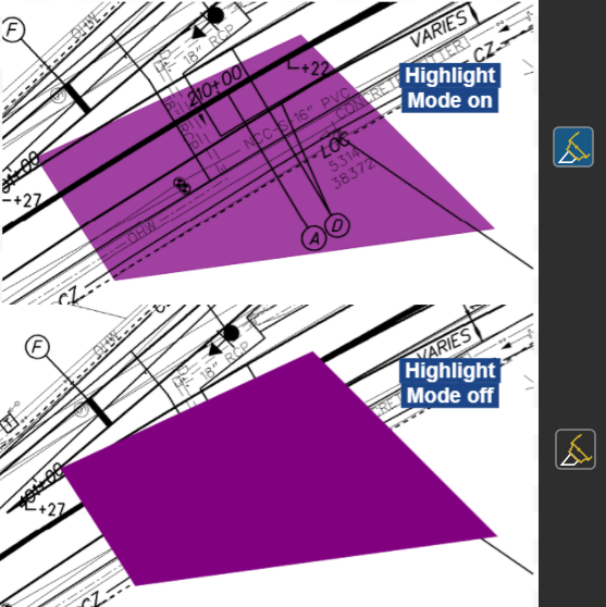
2.4.4. Highlight Mode allows text to be seen through a polygon. By default, Bluebeam Resources from the toolbox should have Highlight mode on. You can toggle this property by clicking on the highlighter icon in the top properties bar. ! A blue tint means Highlight Mode is active.
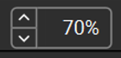
2.4.5. Opacity can be customized in the top properties panel by typing specific values into the field next to Fill: or by using the up and down arrows.
2.5 Sketch to Scale.
Sketch to Scale tools can be polygons, polylines, or ellipses. They allow users to set the exact properties of each shape or line segment. ! Sketch to Scale resources can be used to estimate quantities to get an approximate cost on projects.
2.5.1. Click once on your Sketch to Scale resource from the Tool Chest.

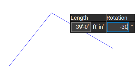
2.5.2. Click on the plan sheet. Take note of the context menu that pops up near your cursor. The fields will change based on the tool you are using and the values will change as you move your cursor.
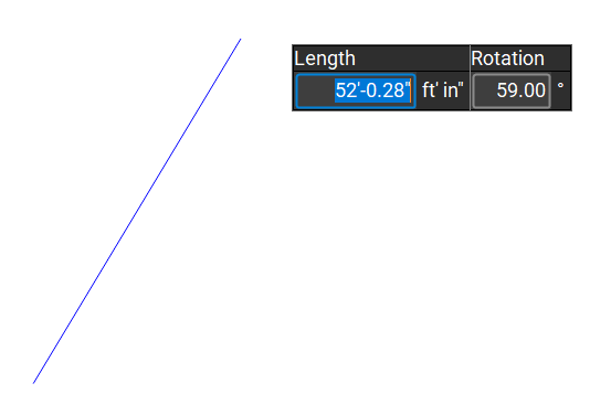
2.5.3. To lock in specific measurements, keep your cursor still and use the keyboard to type in the value you want. Use the Tab button to switch back and forth between fields and press Enter to save that segment. Without moving the mouse, repeat as necessary. ! If you ever lose control over the values in the fields (ex switching tabs, etc), navigate back to Bluebeam without clicking. Once the cursor follows your mouse in Bluebeam, press the mouse scroll wheel.
2.5.4. To freehand points, move the mouse and click to place the next vertex, or press the Enter key with the mouse hovering over the location desired.
2.5.5. When finished, double-click or press Enter twice on your keyboard. ! If a line is finished with an additional unwanted point, it can be removed by subtracting a Control Point. See section 4.2 for more details.
2.5.6. Additional Notes on Sketch to Scale Tools
2.5.6.1. At the top of the application, you’ll see many additional options specific to the Sketch to Scale tools.
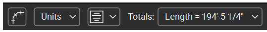
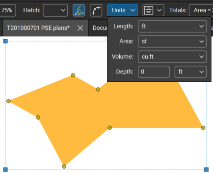
2.5.6.2. Units for measurements can be changed in the Units dropdown.
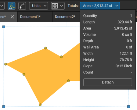
2.5.6.3. The Totals dropdown displays various properties and measurements about the Sketch to Scale resource just created. ! This dropdown can be displayed in its own dialog box by clicking the Detach button. This allows users to move the Totals dialog box anywhere on the screen for improved accessibility.
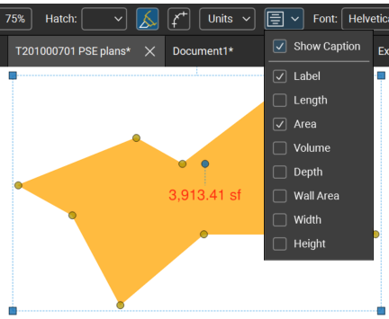
2.5.6.4. Measurements can be directly displayed on the Sketch to Scale resource by checking the Show Caption box and customizing options in the Show Caption dropdown.
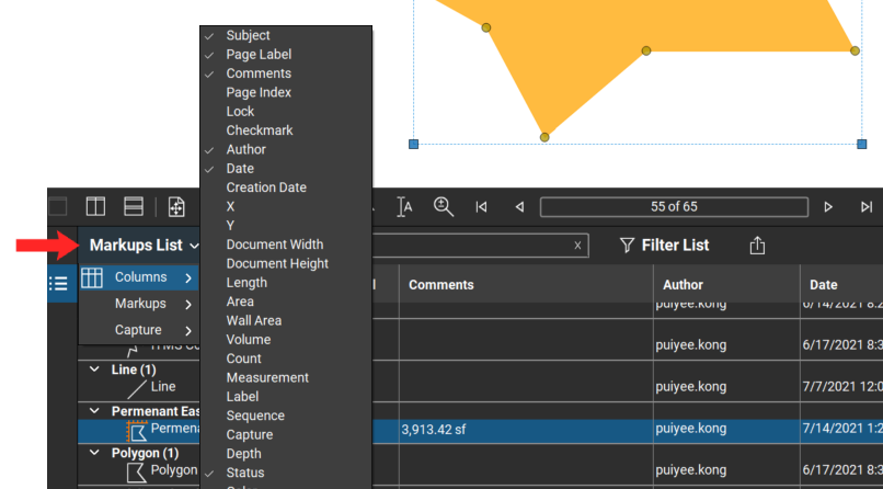
2.5.6.5. Users may customize properties displayed in the Markups List by clicking the arrow next to Markups List > Columns towards the bottom of the page. Select any column options as needed. ! If you do not see the Markups panel, press Alt + L on your keyboard.
2.6 Cell Resources.
Cell Resources are groups of elements that can be placed directly onto the plan sheet. Examples of Cell Resources are Signs, Catch Basins, Signal Heads, Mast Arms, etc. ! See section 4.6 for more on grouping and ungrouping.
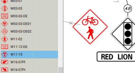
2.6.1. Select a Cell Resource from the Tool Chest.
2.6.2. Click once on the plan sheet wherever you want to place the cell resource.
Note: most cell resources are groups of elements, so changing any of their properties, such as fill or line color, will cause unintended consequences. In order to change the color of a cell resource, navigate to the Properties panel on the right-hand side of the application and click on Change Colors.... Select a new color for the Destination Color and click OK when finished. ! The cell resources were designed with highlight mode on so they do not cover up the content. For more on Highlight Mode, see section 2.4.4.
2.7 Manipulating Resources.
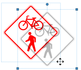
2.7.1. To move an element in Bluebeam, click and drag it to where you want it to go.
Note: In the screencap below, the grey outline is the resource's original location while the colored outline indicates the new position it is being moved to. ! See section 2.1 for more about snapping while moving elements.
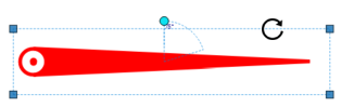
2.7.2. To rotate an element, select it and drag the circular handle at the top to rotate. ! By default, Bluebeam rotates objects by increments of 15 degrees. Hold down the Shift button while rotating to rotate to any angle as necessary.
3. DelDOT Resources
These resources are unique and were created to meet specific DelDOT needs. This section will go into greater depth about how to manipulate and utilize these resources.
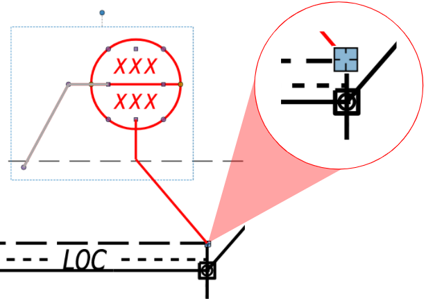
3.1 Identifiers.
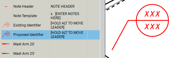
3.1.1. Select an identifier from the Tool Chest. For example, these can be found in the Signal Plans Tool Chest.
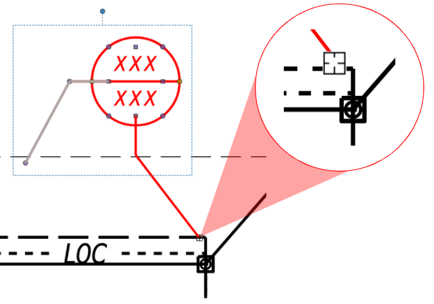
3.1.2. Click once on your plan sheet wherever you want to place the circular head of the identifier.
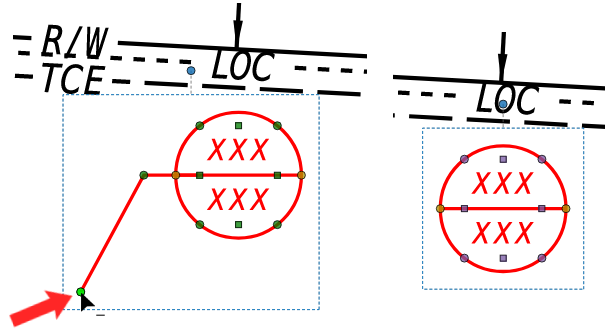
3.1.3. With the identifier selected, hold the Alt key to see all the individual vertices.
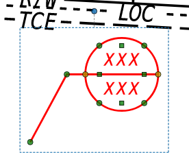
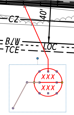
3.1.4. Still holding the Alt key, click the end point of the leader line and drag to the appropriate place on the plan.
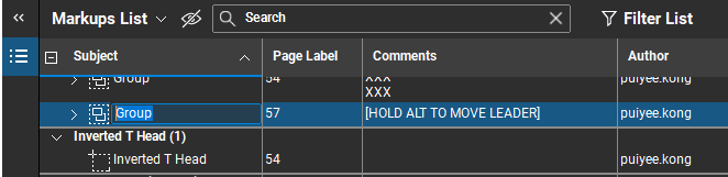
3.1.5. Double click the XXX inside the identifier head to edit the text. Simply hit the down arrow key to navigate down and change the bottom XXX values.
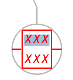
3.1.6. Click into white space to save the edits to the XXX values. ! If the comment cell already has commentary in [ALL CAPS WITH BRACKETS], be sure to delete it before typing comments as it is simply meant provide directions and reminders for users.
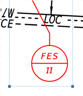
3.2 Removing Leaders from Identifiers.
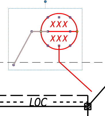
3.2.1. With the identifier selected, hold the Alt key to see all the individual vertices on the identifier.
3.2.2. Still holding the Alt key, hold the Shift key down. A ' − ' icon should appear by the mouse cursor. Click the endpoint of the leader line to remove the leader line.
3.3 Schedules.
Please note: The Schedule resources are still currently under development. Please send an email to DOT CADDSupport@delaware.gov with requests for certain schedules to be added in.
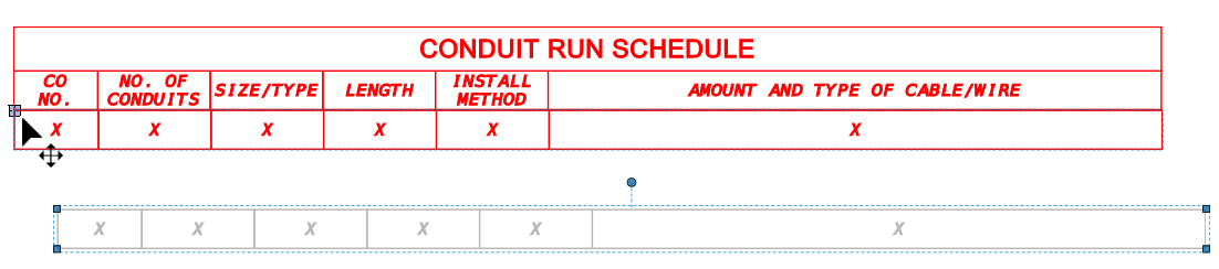
3.3.1. Select a schedule header from the Tool Chest. For example, these can be found in the Signal Plans Tool Chest.
3.3.2. Click once on your plan sheet wherever you want to place the Schedule Header
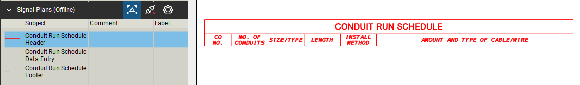
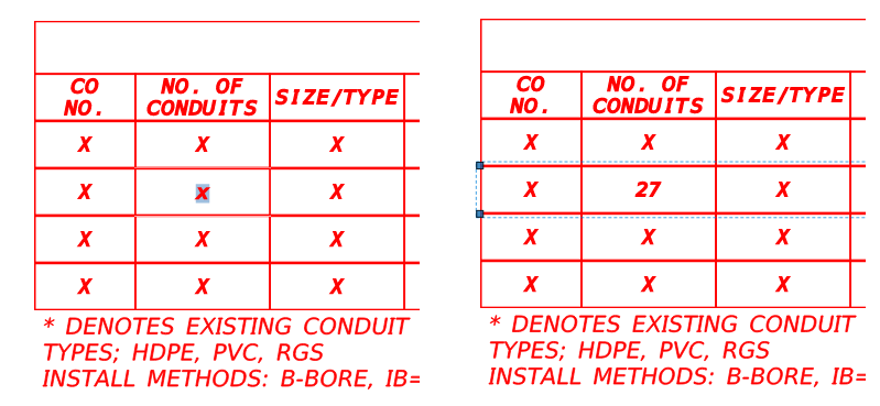
3.3.3. Grab a Schedule Data Entry resource from the Tool Chest and place it anywhere on the sheet
3.3.4. Click near the top left corner of the Schedule Data Entry resource and snap it to the bottom line of the Schedule Header ! When placing or dragging an item, the "snap point" is based nearest to where you clicked to drag the item.
3.3.5. Repeat steps 3.3.3.-3.3.4. as needed to place more rows into the schedule. Follow this process to add a Schedule Footer to the bottom of the schedule as well.
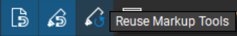
Note: Turning your "Reuse Markups" snap tool on allows you to continue to place multiple of the same element after placing the first. The option to turn this on can be found in the snap bar at the bottom right of the screen. ! Holding the Ctrl key and dragging an element allows you to duplicate it.
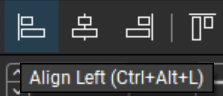
3.3.6. Please note that the data entry rows will not be aligned when placed; this is normal. To align them, select the schedule elements to be aligned, and click the Align Left button from the Alignment panel located at the top of the screen. ! Right-click and drag to create a blue selection window, dragging from right to left will select anything in and crossing the blue selection window while dragging left to right will only select items completely contained within the blue selection window.
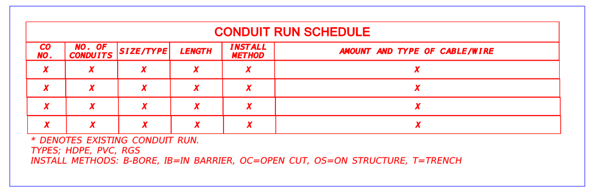
3.3.7. Click into the white space to deselect the schedule.
3.3.8. Double click on any "x" to edit the text. Click into the white space to save the changes to text.
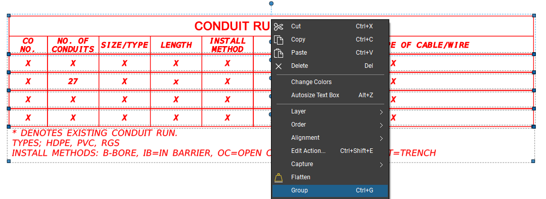
3.3.9. Once the schedule is fully updated with information, select the entire schedule and right click and select Group from the menu.
4. Advanced Manipulation
This section will walk the user through advanced manipulation of elements. These steps will likely be used less often and in more specialized scenarios.
4.1 Line segment to Arc.
Note: This step only applies to polyline and polygon elements.
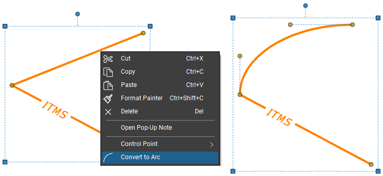
4.1.1. Right click a line segment.
4.1.2. Click Convert to Arc. ! See section 4.4 for more on Manipulating Arcs/Curves
4.2 Adding and Subtracting Control Points.
A control point defines where two segments meet in multi-segment elements. It appears as a yellow circle on lines, polylines, and borders of polygons. Note: Some resources, such as ellipses, do not have the option to edit control points.
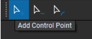
4.2.1. To add a control point, right click along a line segment and select Control Point > Add Control Point to add a point. ! Clicking along the line segment while holding the Alt + Shift keys will add a Control Point.

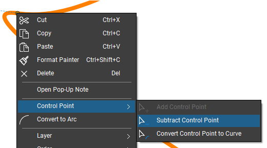
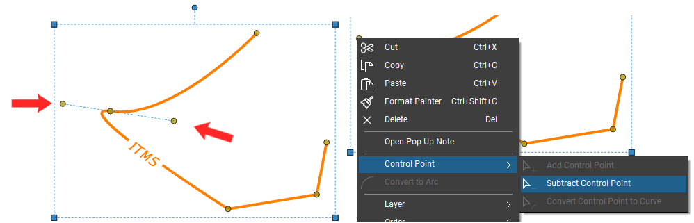
4.2.2. To subtract a control point, right click a specific point and select Control Point > Subtract Control Point to remove the selected point. ! Clicking a Control Point while holding the Alt + Shift keys will remove the Control Point.
4.2.3. The above can be done via the tools in the Control Point toolbar in the properties bar at the top of the screen.
4.3 Control Point to Curve.
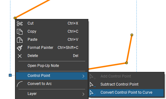
4.3.1. Right click a point along a line segment.
4.3.2. Select Control Point > Convert Control Point to Curve from the menu.
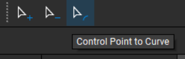
4.3.3. The above can also be done via the Control Point to Curve tool in the Control Point toolbar at the top of the screen.
4.4 Manipulating Arcs/Curves.
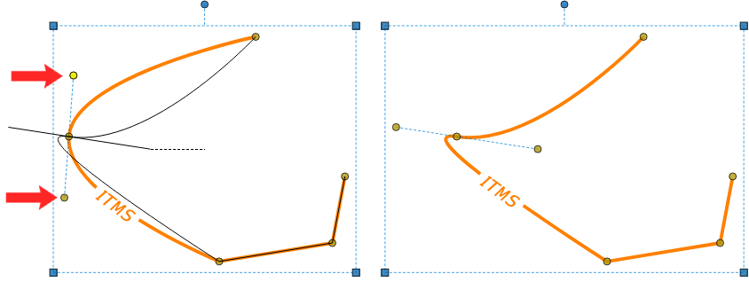
4.4.1. Drag the control points at either end of the dotted blue lines to modify the arc as necessary. ! Holding the Alt + Ctrl keys on a control point can convert it to an arc. You can drag out to immediately edit or modify the curve.
4.5 Removing Arcs/Curves.
4.5.1. Right click on the control points at either end of the blue dotted lines. Select Control Point > Subtract Control Point from the menu. Repeat as necessary. ! Holding the Shift key and clicking on a desired point will also subtract it.
4.6 Adding a Leader to Identifiers.
Identifiers are comprised of a callout and a horizontal divider line in the middle of the identifier head.
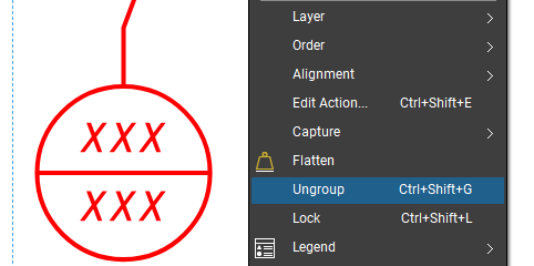
4.6.1. Right click the identifier and select Ungroup.
4.6.2. Click into the white space to deselect everything.
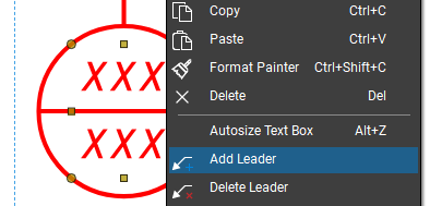
4.6.3. Right click the identifier, and select the Add Leader option from the menu. ! Holding the Shift key while clicking on the Control Point at the bend of the leader will also allow you to place a new leader.
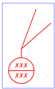
4.6.4. Move the mouse cursor around to set the position of the new leader and click to save it. You can adjust the location of the leader afterwards by clicking and dragging.
4.6.5. Right click in the white space to the right of the identifier and drag to select the entire identifier. Let go once a blue rectangle captures the entire identifier.
4.6.6. Right click the horizontal line running inside the identifier head. Select Group from the menu. ! It is crucial to group after clicking the horizontal line so that comments to the identifier remain intact and correct.
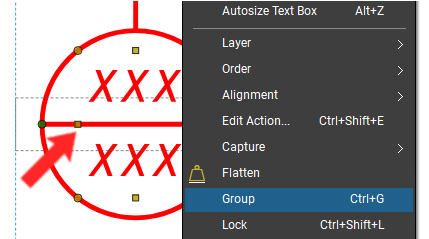
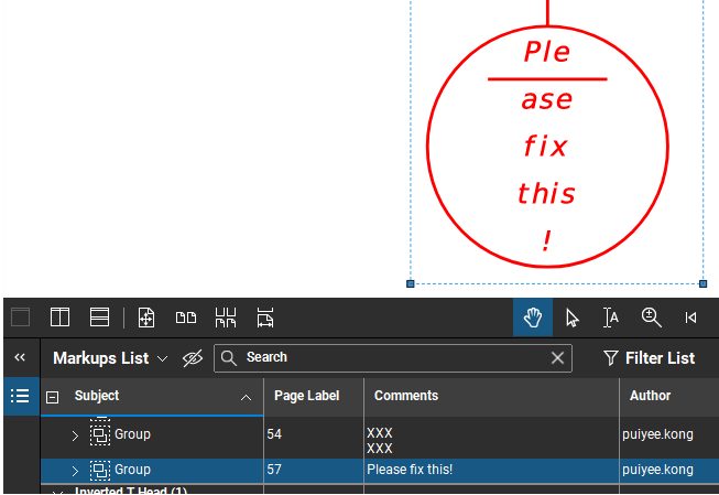
Note: If you do not properly group the identifier by the horizontal line, the comment will show the text within the identifier itself. This means that if a comment is added to the identifier, the commentary will replace the text in the identifier. If this happens, use the Ctrl + Z keys to undo the commentary and ungroup the identifier once more. Follow step 4.5.6. again using the horizontal line to group.
4.6.7. Rename the group to the proper resource name and replace bracketed text with comment as appropriate.