Difference between revisions of "CADD Standards - 2010 Edition"
From DelDOT CADD Wiki
Mbalbierer (talk | contribs) |
|||
| Line 29: | Line 29: | ||
</p> | </p> | ||
<p> | <p> | ||
DelDOT has adopted '''MicroStation''' and '''InRoads''' as its standard drafting and design software packages respectively. These standards have been developed and tested using the | DelDOT has adopted '''MicroStation''' and '''InRoads''' as its standard drafting and design software packages respectively. These standards have been developed and tested using the software versions available at the following Wiki Page: | ||
<ul> | <br> | ||
[[DelDOT CONNECT CADD Standards Installation - CR2102]] | |||
<!--<ul> | |||
<li>MicroStation V8i (SELECT series 4) – Version 08.11.09.832</li> | <li>MicroStation V8i (SELECT series 4) – Version 08.11.09.832</li> | ||
<li>MicroStation CONNECT Edition Update 5 – Version 10.05.00.40</li> | <li>MicroStation CONNECT Edition Update 5 – Version 10.05.00.40</li> | ||
| Line 36: | Line 38: | ||
<li>InRoads V8i (SELECT series 4) – Version 08.11.09.878</li> | <li>InRoads V8i (SELECT series 4) – Version 08.11.09.878</li> | ||
<li>Microsoft Windows 10 – 64 bit</li> | <li>Microsoft Windows 10 – 64 bit</li> | ||
</ul> | </ul>--> | ||
</p> | </p> | ||
<p> | <p> | ||
Revision as of 10:38, 16 November 2022
Preface
It gives me great pleasure to introduce the Delaware Department of Transportation (DelDOT) CADD Standards - 2010 Edition. A great deal of work and coordination with representatives from DelDOT and the consulting community went into the development of these CADD Standards.
This latest edition of the DelDOT CADD Standards outlines the best practices you must follow for all DelDOT related engineering work, whether you work at DelDOT and produce CADD drawings and models, or are a consultant responsible for design drawings and model deliverables for DelDOT projects.
The resource files that support these CADD Standards, such as seed files, cell libraries and Menu Bars are available for download. Directions for downloading the resource files can be found under Resources > Guidance.
The standards have been developed to assist you and should be considered as dynamic standards that will evolve over time to better serve you. Should you have any questions, concerns, or suggestions for improving the content of these CADD Standards and supporting resource files, please send an email to DOT_CADDSupport@delaware.gov.
Natalie Barnhart
Chief Engineer
DelDOT
800 Bay Road
Dover, Delaware 19903
May 11, 2010
Introduction
About This Manual
Computer Aided Drafting and Design (CADD) is the preferred method of preparing contract plans for DelDOT. The standardization requirements presented in these standards ensure that CADD files can be used by the entire project team (surveyors, planners, designers, reviewers and contractors) throughout all phases of project development and delivery.
DelDOT has adopted MicroStation and InRoads as its standard drafting and design software packages respectively. These standards have been developed and tested using the software versions available at the following Wiki Page:
DelDOT CONNECT CADD Standards Installation - CR2102
These CADD Standards supersede all DelDOT CADD Standards previously published.
The CADD Standards do not exempt the professional from performing responsible surveying and/or engineering. They are intended to provide uniform procedures and standards for organizations that perform CADD related services for DelDOT. The professional shall have final responsibility for the accuracy of all input and output of computer based applications.
Revisions and Updates
The CADD Standards were developed through input from DelDOT staff, as well as the consultant and construction communities. DelDOT’s Office of Performance Management (OPM) - CADD Section will develop and maintain procedures and standards for DelDOT’s CADD related activities. CADD users are encouraged to submit comments and suggestions for improvements to the DelDOT’s CADD standards and supporting resource files. Any errors found should be emailed to DOT_CADDSupport@delaware.gov.
DelDOT strives to stay current with state of the art trends in the market. However, impacts on project delivery schedules and resources necessary to provide support for new features must be considered prior to any change.
Updating to the CADD Standards and supporting resource files is intended to be a continuous process and revisions will be issued periodically.
Trademarks
MicroStation and InRoads are registered trademarks of Bentley Systems, Incorporated. Other trade names, computer protocols and file formats mentioned in the CADD Standards are the trademarks of their respective owners. In no event will the appearance of any graphic, description of any graphic, picture, screen display or any other method of conveying meaning be considered to impair the rights of the respective owners.
Chapter 1 - DelDOT CADD Network
DelDOT Servers
There are at least eight different servers within DelDOT that are used for CADD files and supporting resources. The uses of these servers are dictated primarily by the location of the user and are listed in the following table.
| Server Name | Primary Use of Server |
|---|---|
| DOTASCADD01 |
|
| DOTASCADD04 |
|
| DOTFS08 |
|
Typical Drive Mappings
| Drive Letter | Drive Mapping and Description |
|---|---|
| K:\ |
|
| T:\ |
|
| U:\ |
|
| V:\ |
|
| Y:\ |
|
MicroStation V8i Resource Locations
MicroStation V8i resources are located in the Y:\msv8 folder. Old references to “msvj” or “pre_msv8” within the directory structure have been removed. There should be no more resources that pertain to the old design file level structure of 1-63.
| Folder Name | Folder Description/Contents |
|---|---|
| Y | \\dotfs08\CADD\Active_Designs |
| msv8 | MicroStation V8i References |
| cell | Cell Library Main Folder |
| dgnlib | MicroStation DGN Libraries (Levels, Templates, etc) |
| Fonts | MicroStation Font Resource Files |
| shx | AutoCAD Font Files |
| ttf | TrueType Font Files |
| InRoads | General InRoads Files |
| dgnlib | InRoads DGN Libraries (Civil Features, Design Standards, etc.) |
| Roundabouts | InRoads (SS2) Add-in for Roundabout Creation |
| ss | InRoads (SS2) Storm and Sanitary Data Files |
| Superelevation | InRoads (SS4) Superelevation Rate Data Files |
| TIW | InRoads (SS4) Survey Text Import Wizard Files |
| XML Data | InRoads (SS2/SS4) XML Report Formats |
| xs | InRoads (SS2/SS4) Cross Section Titleblock Data Files |
| materials | MicroStation Materials for Visualization |
| mdlapps | MDL Applications |
| pentables | Plotting Pen Tables |
| pltcfg | MicroStation Print/Plot configuration files |
| prefs | Standard MicroStation user setup |
| References | General Reference Files |
| gis_data | General References to GIS Data and Aerials |
| Maps | County Maps, District Maps and Signal Maps |
| Seed | MicroStation Seed Files |
| VBA | Visual Basic Application Files for MicroStation |
MicroStation CONNECT Edition (MSCE) Resource Locations
MicroStation CONNECT resources are located in the Y:\msce folder. The majority of files should be identical to their counterparts within the MicroStation V8i resource folder, but just rearranged for the newer MicroStation CONNECT folder structure.
| Folder Name | Folder Description/Contents |
|---|---|
| Y | \\dotfs08\CADD\Active_Designs |
| msce | MicroStation CONNECT References |
| cell | Cell Library Main Folder |
| data | MicroStation Settings Files (Color Tables, Unit Definitions, etc.) |
| dgnlib | MicroStation DGN Libraries (Levels, Templates, etc.) |
| Fonts | MicroStation Font AutoCAD and TrueType Font Files |
| Macros | Visual Basic Application Files for MicroStation |
| materials | MicroStation Materials for Visualization |
| mdlapps | MDL Applications |
| pltcfg | MicroStation Print/Plot configuration files |
| prefs | Standard MicroStation user setup |
| References | General Reference Files |
| gis data | General References to GIS Data and Aerials |
| Maps | County Maps, District Maps and Signal Maps |
| Seed | MicroStation Seed Files |
| Symb | MicroStation Font and Line Style Resource Files |
| Tables | Plotting Pen Tables |
| WorkSpaces | MicroStation CONNECT DelDOT WorkSpaces |
Chapter 2 - Directory and File Naming
Specific guidelines have been established for the naming of contract directories and files. These guidelines must be followed to ensure that programs relying on this naming structure function correctly. This naming structure also ensures the efficient sharing and transfer of information between DelDOT staff, consultant staff and contractors. This chapter outlines the comprehensive naming convention for all project files used in the CADD environment.
Directory Naming
Project specific working directories for all construction projects are located on the Y-Drive at the following address: [file://dotfs08/CADD/active_designs/ \\dotfs08\CADD\active_designs\] . The main project directory is labeled with the construction contract number, with subdirectories created under this main directory using the follow naming convention.
| Folder Name | Folder Description/Contents |
|---|---|
| Y | Y-Drive |
| Sussex | County Location |
| 014 | Maintenance Road Number |
| Road | Department Management Section |
| 2001303 | Main Project Directory (Contract #) |
| Correspondence | Project Specific Correspondence |
| InRoads | InRoads Data Files |
| Cogo | COGO Data Files & Reports |
| Dtm | Digital Terrain Model Files |
| Photos | Project Specific Photos |
| Plans | MicroStation Design Files (.DGN) |
| Plot | Construction Plan Plot Files |
| RWPlot | Right-of-Way Plot Files |
| Survey | Files Created by Survey Section (Un-Edited Copies) |
| XSPlot | Cross Section Plot Files |
General File Naming
Standard file name extensions for information submitted to or exchanged with DelDOT shall be as follows:
| File Type | Extension |
|---|---|
| MicroStation Design Files | .dgn |
| MicroStation Cell Libraries | .cel |
| MicroStation Resource Files | .rsc |
| InRoads Preference Files | .xin |
| InRoads COGO Data Files (Input Files) | .dat or .ics |
| InRoads COGO Report Files (Output Files) | .rpt |
| InRoads Digital Terrain Model Files | .dtm |
| eQuorum Plot Request Files | .prf |
| Adobe Acrobat Files/Electronic Plot Submission Files | |
| Microsoft Word Documents | .doc |
| Microsoft Excel Worksheets | .xls |
Spaces or special keyboard characters shall not be used in the file name. Special characters are ~`!@#$%^&*):(-+=”\}|{;][’>.<?,/. For file types not listed above, the default file extension defined by the software shall be used.
Design File Naming
MicroStation design file names shall use the following convention:
CategoryNum.dgn (Ex: CP03.dgn or FS00.dgn)
Category = This portion of the file name is established by using the two letter standard corresponding to the desired design file category listed in the section entitled Design File & IPARM File (.i) Categories.
Num = This portion of the file name describes the number/type of a design file. Strip files (files that encompass the entire length of a design) should be denoted with a 00. Sheet files should start with 01 and sequentially increase for each sheet of the same category.
Design File & IPARM File (.i) Categories
| Description | Design File Category | IPARM Category | Design Script |
|---|---|---|---|
| Alignment Layouts † | AL | AL | deldot_plans.dscript |
| Addenda and Revisions | AR | AR | |
| Arch Bridge Details | AD | AD | |
| Boring Log | BO | BO | |
| Bridge Abutment Details | AB | AB | |
| Bridge Approach Slab Details | AS | AS | |
| Bridge Beam Details | BM | BM | |
| Bridge Bearing Details | BB | BB | |
| Bridge Camber Table | CT | CT | |
| Bridge Composite Details | CO | CO | |
| Bridge Deck Plan | DK | DK | |
| Bridge Footing Plan | FT | FT | |
| Bridge Framing Plan | FR | FR | |
| Bridge Headwall Details | HW | HW | |
| Bridge Parapet Details | PA | PA | |
| Bridge Pier Details | PR | PR | |
| Bridge Pile Details | PL | PL | |
| Bridge Plan and Elevation | PE | PE | |
| Bridge Rail Details | RA | RA | |
| Bridge Rehabilitation Details | RH | RH | |
| Bridge Rigid Frame Details | RF | RF | |
| Bridge Sheet Pile Details | SH | SH | |
| Bridge Slope Protection Details | SP | SP | |
| Bridge Special Structure Details | ST | ST | |
| Bridge Timber Structure Details | TD | TD | |
| Bridge Wick Drain Layout Sheet | WD | WD | |
| Bridge Wingwall Details | WW | WW | |
| Construction Plan Sheet * | CP | CP | |
| Construction Plans | - | CP | |
| Environmental Compliance | - | EC | |
| Grades & Geometric Plans | - | GG | |
| Landscaping Plans | - | LS | |
| Lighting Plans | - | LI | |
| Right of Way Plans | - | RW | |
| Signing, Signing and Conduit Plans | - | SS | |
| Utility Relocation Plans | - | UT | |
| Construction Sequence/Phasing † | CS | CS | |
| Construction Title Sheet | TC | TC | |
| Cross Sections | XS | XS | |
| Culvert Details | CU | CU | |
| Detour Plan | DP | DP | |
| Display / Presentation | DI | DI | |
| Expansion Joint | EX | EX | |
| Field Survey/Existing Topography † | FS | FS | |
| Finished Bridge Deck Elevations | FD | FD | |
| General & Project Notes | PN | PN | |
| Horizontal and Vertical Control | HV | HV | |
| Hydrology / Drainage Areas † | HY | HY | |
| Index Sheet | IS | IS | |
| Landscaping Details | LS | LS | |
| Legend Sheet (Construction & Right-of-Way Plans) | LG | LG | |
| Lighting † | LI | LI | |
| Miscellaneous Details | DT | DT | |
| Model File | MD | MD | |
| Profiles | PF | PF | |
| Project Sheet Border | SB | SB | |
| Proposed Construction † | PC | - | |
| Reinforcing Bar Summary | BR | BR | |
| Retaining Wall Details | RD | RD | |
| Right of Way † | RW | RW | |
| Right-of-Way Metes and Bounds | RB | RB | |
| Right-of-Way Mosaic | RM | RM | |
| Right-of-Way Tabulation | RT | RT | |
| Right-of-Way Title Sheet | TR | TR | |
| Shape / Shading File † | SF | SF | |
| Signalization Plan | SG | SG | |
| Storm Water Management | SW | SW | |
| Structure Removal | SR | SR | |
| Superelevation Diagrams & Charts | SE | - | |
| Typical Sections | TS | TS | |
| Utilities † | UT | UT | |
| Work File (Miscellaneous Line Work) | WK | WK |
† = Design file encompasses the entire project area (Strip Design File).
* = Multiple plan sheets are generated from this design file.
IPARM File (.i) Naming
eQuorum plot request file names shall use the following convention:
NumCat.i (Ex: 001TC.i or 012CP.i)
Num = This portion of the file name denotes the sheet number of the contract set that the plot request file is generating. This number shall be three characters in length.
Cat = This portion of the file name is established by using the two letter standard corresponding to the desired plot request file category listed in the section entitled Design File & IPARM File (.i) Categories.
Electronic Plot File (PDF) Naming
Electronic plot file names shall use the following convention:
CatNum.pdf (Ex: CD001.pdf or RW012.pdf)
Cat = This portion of the file name is established by using the two letter standard corresponding to the desired electronic plot file category listed below.
- RD = Road Construction Plan Set
- BD = Bridge Construction Plan Set
- ES = Erosion and Sediment Control Plan Set
- TR = Traffic Plan Set
- RW = Right-of-Way Plan Set
- XS = Cross Section Set
Num = This portion of the file name denotes the corresponding sheet number of the contract set that is being generated by the PDF file. This number shall be three characters in length.
Chapter 3 - Design Standards
Seed Files
MicroStation uses a seed file to create all design files. A seed file is a template in which standard design file parameters are set. Seed files do not typically contain elements, but similar to design files they contain file settings such as global origin, working units and view configurations. Using a standard, customized seed file helps maintain uniformity and keeps the user from having to adjust design file settings each time a file is created.
The following two dimensional (2D) and three dimensional (3D) seed files are available on the DelDOT DRC website and shall be used in the preparation of plans for submission to DelDOT. Unless otherwise directed the “deldot_seed2d_in.dgn” and “deldot_seed3d_in.dgn” files are to be used for structural details only.
| Dimension | Seed File Name |
|---|---|
| 2D |
|
| 3D |
|
Note: The MicroStation configuration variable MS_DESIGNSEED is used to define the default seed file.
Working Units
MicroStation allows the user to draw in real world units such as feet, inches, meters, etc. These real world units are called working units. Working units are expressed in Master Units (the largest units in common use in a design file, such as feet) and fractional Sub Units (such as tenths or inches).
The default definition for the foot in MicroStation is the International Foot. The Delaware State Plane Coordinate System upon which all DelDOT roadway and bridge design projects are based is measured in U.S. Survey Feet. Therefore, DelDOT uses the U.S. Survey Foot definition, and not the International Foot, as the standard Master Unit.
U.S. Survey Feet: 1 foot = 1200/3937 meters = 0.3048006 meters
XXX International Feet: 1 foot = 0.3048000 meters XXX
DelDOT has developed a standard unit definition file, deldot_custom_unit_definitions. , to define the U.S. Survey Foot as the standard Master Unit. This file can be obtained from the DelDOT DRC website.
MicroStation design files used in plan preparation shall use the following standard working units as defined in the DelDOT seed files and in the deldot_custom_unit_definitions.def file.
| Unit Description | Value | Label |
|---|---|---|
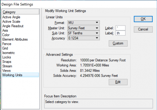
| Master Unit | Survey Feet | ‘ |
| Sub Unit | SF Tenths | th |
The DelDOT seed files have been created with the standard working units described above and with a standard resolution setting of 10,000 per Distance Survey Foot. These settings shall not be changed by the user.
Note: The MicroStation configuration variable MS_CUSTOMUNITDEF is used to specify the active unit definition file.
Global Origin
Elements in the design file are created by placing data points. Each data point placed in the design file has associated X (Easting), Y (Northing) and Z (Elevation, 3D files only) positions or coordinates.
In the DelDOT seed files, the point called the Global Origin is set to the design files exact center and assigned the coordinates 0,0 (2D files) and 0,0,0 (3D files). The Global Origin as defined in the DelDOT seed files should never be changed by the user for DelDOT projects.
Note: Each element placed in a design file shall be geographically correct relative to the Delaware State Plane Coordinate system. Horizontal coordinates shall be based on the North American Datum of 1983 (NAD83). Vertical elevations shall be based on the North American Vertical Datum of 1988 (NAVD88).
Coordinate Readout
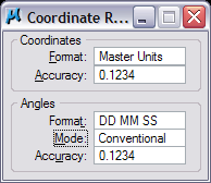
The coordinate readout settings that are delivered in the DelDOT standard seed files are shown in Figure 1. As mentioned previously in the section entitled Working Units, the DelDOT seed files are created with the resolution equal to 10,000 per Distance Survey Foot. This setting shall not be changed by the user.
Drawing Scale
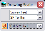
The Drawing Scale dialog box allows the scale of a drawing to be changed at any time by selecting the appropriate scale factor from the Drawing Scale dialog box. When selected, the scale factor is stored within the design file and affects the scale dependent items such as text, cells and line styles.
All of the scale dependent drawing elements such as text, cells and line styles have been redefined in the new CADD Standards at a unit scale of 1:1. These elements are then automatically scaled up or down by the drawing scale factor as they are selected from the DelDOT Menu Bar. This helps maintain consistency of scale-dependent drawing features, regardless of the scale being used.
Note: The Drawing Scale dialog box can be activated by entering dialog drawingscale open in the MicroStation Key-In command line. The Drawing Scale dialog box can also be activated by choosing DelDOT Common > Set Model Scale/Working Units from the DelDOT Menu Bar.
The standard DelDOT drawing / annotation scales used in the preparation of DelDOT plan sets are defined in the DelDOT_Custom_Scales.def file, and can be obtained from the DelDOT DRC website.
Note: The MicroStation configuration variable MS_CUSTOMSCALEDEF is used to assign the scale definition file.
Engineering scales shall be used for all roadway sheets and for bridge plan view sheets. Architectural scales are used for annotating bridge details and occasionally roadway details. The following drawing / annotation scales have been defined in the deldot_scales.def file:
| Engineering | Scale |
|---|---|
| Full Size 1=1 | 1:1 |
| ENGR 1:2 | 2:1 |
| ENGR 1:5 | 5:1 |
| ENGR 1:10 | 10:1 |
| ENGR 1:20 | 20:1 |
| ENGR 1:25 | 25:1 |
| ENGR 1:30 | 30:1 |
| ENGR 1:40 | 40:1 |
| ENGR 1:50 | 50:1 |
| ENGR 1:60 | 60:1 |
| ENGR 1:100 | 100:1 |
| ENGR 1:120 | 120:1 |
| ENGR 1:200 | 200:1 |
| ENGR 1:250 | 250:1 |
| ENGR 1:300 | 300:1 |
| ENGR 1:400 | 400:1 |
| ENGR 1:500 | 500:1 |
| ENGR 1:600 | 600:1 |
| ENGR 1:1000 | 1000:1 |
| Architectural | Scale |
|---|---|
| Full Size 1=1 | 1:1 |
| ARCH 1/32 : 1 | 32:1 |
| ARCH 1/16 : 1 | 16:1 |
| ARCH 3/32 : 1 | 32:3 |
| ARCH 1/8 : 1 | 8:1 |
| ARCH 3/16 : 1 | 16:3 |
| ARCH 1/4 : 1 | 4:1 |
| ARCH 3/8 : 1 | 8:3 |
| ARCH 1/2 : 1 | 2:1 |
| ARCH 3/4 : 1 | 4:3 |
| ARCH 1 ½ : 1 | 2:3 |
| ARCH 3 : 1 | 1:3 |
| ARCH 6 : 1 | 1:6 |
| ARCH 12 : 1 | 1:12 |
Recommended sheet scales are listed in the following table:
| Sheet Type | Scale |
|---|---|
| Plan Sheet – Urban | ENGR 1:30 |
| Plan Sheet – Rural (Check with DelDOT Project Manager prior to utilizing this scale.) | ENGR 1:50 |
| Plan Sheet – Bridge | ENGR 1:30 |
| Profile – Horizontal | Match Plan Sheet Scale |
| Profile – Vertical | 10 Times the Horizontal Scale |
| Typical Sections | ENGR 1:5 |
| Detail Sheets | Architectural Scales |
Annotation Scale
The Annotation Scale lock found on the dialog boxes for text, cells and line styles provides control for the size of elements as they are placed in the design file. As elements are placed into a design file, they should be placed with the Annotation Scale Lock set to on. Enabling the Annotation Scale Lock at the time elements are placed within the design file allows for automatic rescaling of these items if the design file drawing scale is modified in the future.
The standard DelDOT annotation scales used in the preparation of DelDOT plan sets are defined in the DelDOT_Custom_Scales.def file, and can be obtained from the DelDOT DRC website.
Colors
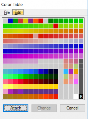
Each element in a MicroStation design file is assigned a color number to ensure consistency and allow users to easily identify plan elements in shared files. MicroStation reads a color table to determine the correct color display for a particular color number. The DelDOT standard color table, deldot_color.tbl, can be obtained from the DelDOT DRC website.
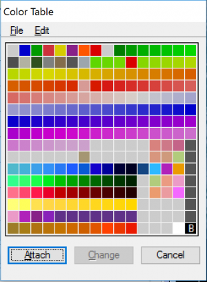
A color table to be used for visualization purposes, that ties directly to the InRoads components, has been provided as well. The DelDOT visualization color table, deldot_color_visualization.tbl, can be obtained from the DelDOT DRC website.
Note: The MicroStation configuration variable MS_DEFCTBL is used to specify the active color table.
Fonts
DelDOT has defined several standard fonts for use on all plans. It is important to use these fonts so that the final plotted version of the plans matches the electronic display version of the file. Only the fonts listed below are acceptable for use on plans prepared for DelDOT.
Note: The MicroStation configuration variable MS_SYMBRSC is used to specify the font library.
The standard DelDOT fonts used in the preparation of DelDOT plan sets are listed below and can be obtained from the DelDOT DRC website.
| Font Name | Font Type |
|---|---|
| DelDOT Eng Heavy | TrueType |
| DelDOT Eng Mono Heavy | |
| DelDOT Eng Vert | |
| DelDOT Eng Vert Heavy | |
| DelDOT Eng Vert Mono | |
| DelDOT Eng Vert Mono Heavy | |
| DelDOT Titles | |
| DelDOT_103 | Default |
| DelDOT_109 | |
| DelDOT_110 | |
| DelDOT_113 | |
| DelDOT_114 | |
| DelDOT_117 |
“Default” fonts are default or unmodified fonts that are shipped with MicroStation and “TrueType" fonts have been modified by DelDOT for use in plan preparation.
Text
In general, all text placed in a design file is placed on the same level as the element that is being annotated. All text is typically placed in the sheet design file and not in a strip design file. The only exception to this would be the annotation of alignment stationing or other text that has been created by InRoads.
Only upper case text shall be used with the text justification set to left-center, except for property ownership information on plan sheets, which is center-center justified. For additional text justification information see the section entitled Text Size.
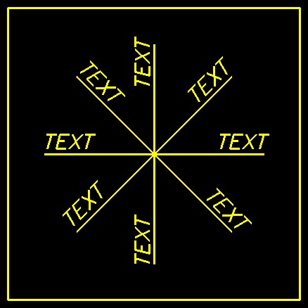
Text is generally placed on plan sheets so that the bottom of the text is aligned with the bottom or right edges of the sheet border. When element labeling requires text rotation, follow the examples in the figure below for direction and position of text at the various rotation angles.
Text Line Spacing
In general, text line spacing of multiples lines of text should equal two-thirds (2/3) the text height. The spacing between paragraphs or individual notes should be equal to the text height being used in the paragraph or note.
Text Size
Standard text sizes have been defined to ensure uniform legibility of all plan sheets. The standard text sizes listed below refers to the size of the text on the finished full size plot, not the text size in the design file. The correct design file text size is dependent upon the intended plot scale. DelDOT standard text sizes are defined as shown in the following table:
| Type of Text | Text Height | Text Width | Text Wt. | Text Just. | Font Name |
|---|---|---|---|---|---|
| Plan Sheets | |||||
| Existing Labeling | 0.100” | 0.080” | 0 | LC | DelDOT Eng Vert |
| Proposed Labeling | 0.125” | 0.100” | LC | DelDOT Eng Heavy | |
| Identifier | 0.100” | 0.080” | CC | DelDOT Eng Heavy | |
| Match Line | 0.250” | 0.200” | CC | DelDOT Titles | |
| Plan Notes | 0.125” | 0.100” | LT | DelDOT Eng Heavy | |
| Roadway Names | 0.125” | 0.100” | CC | DelDOT Titles | |
| Schedule - Titles | 0.1875” | 0.150” | CC | DelDOT Titles | |
| Schedule - Column Header | 0.125” | 0.100" | CC | DelDOT Eng Mono Heavy | |
| Schedule - Data Entry | 0.125” | 0.100” | CC | DelDOT Eng Mono Heavy | |
| Detail Sheets | |||||
| Titles | 0.250” | 0.200” | 0 | CC | DelDOT Titles |
| Sub-Titles | 0.1875” | 0.150” | CC | DelDOT Titles | |
| Dimensions – Proposed | 0.125” | 0.100” | CC | DelDOT Eng Heavy | |
| General Text | 0.125” | 0.100” | LC | DelDOT Eng Heavy | |
| Sheet Borders | |||||
| Project Title | 0.250” | 0.200” | 0 | CC | DelDOT Titles |
| Sheet Description | 0.1875” | 0.150 | |||
| Standard Construction Details Manual Only | |||||
| Notes | 0.090” | 0.070” | 0 | CC | Calibri |
| Subtitles | 0.125” | 0.100” | CC | Calibri | |
| Title Block Large | 0.150” | 0.130” | LB | Imprint MT Shadow | |
| Title Block Medium | 0.125” | 0.100” | LB | Imprint MT Shadow | |
| Title Block Small | 0.050” | 0.040” | LB | Imprint Shadow | |
To calculate text sizes used in a MicroStation design file for various scaled plan sheets, use the following method:
(Standard Text Size) x (Plotting Scale) = Design File Text Size
Example: .125 inch x 30 ft/inch = 3.75 feet
Note: Text heights smaller than 0.100” are not permitted on plans prepared for DelDOT. Text output generated from InRoads is handled by the preferences established in the DelDOT InRoads XM file ('DelDOT_Standards_SS4.xin'). This file can be obtained from the DelDOT DRC website.
Text Styles
A MicroStation Text Style is a set of text parameters such as font type, text width, text height, color, etc. that have been saved for repeated use. Text styles enable the user to place text in a consistent and automated manner.
The standard DelDOT text styles used in the preparation of DelDOT plan sets are defined in the deldot_text_styles.dgnlib MicroStation DGN Library, and can be obtained from the DelDOT DRC website.
Note: The MicroStation configuration variable MS_DGNLIBLIST is used to attach the deldot_textstyles.dgnlib resource file.
The various “Type of Text” items listed on the previous page have been preconfigured in the deldot_text_styles.dgnlib file for use on plans prepared for DelDOT.
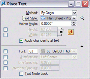
To ensure proper text settings, the active text style should be selected prior to placing text. Also, the Annotation Scale Lock should be on to ensure that the text is being placed at the proper size for the intended drawing scale.
Note: It is important to remember that Text Styles do not set the Level or Weight for text placement. The text however will be placed on the active level with the active weight.
Element Symbology
Each element placed into a MicroStation design file contains a specific setting or attribute for its level, color, line style and weight. The collection of these element attributes is referred to as an element’s symbology. Element symbology is used to differentiate how elements are displayed in the design file and on the final plotted sheet.
By default, there are an unlimited number of MicroStation levels that can be utilized in each design file. DelDOT has defined a specific set of level assignments that are to be utilized in the preparation of DelDOT plan sets.
As mentioned in the section entitled Colors, each element in a MicroStation design file is assigned a specific color number to ensure consistency and allow users to easily identify plan elements in shared files.
By default, there are eight line styles (0-7) available in MicroStation. DelDOT has begun the use of customized line styles to replace previously used linear patterns. Some examples of these custom line styles are fences, ditch lines, guardrail, woods lines, etc.
There are thirty two default line weights (0-31) available in MicroStation. In general, existing topographical features are displayed at a weight of zero (0) and proposed construction features are displayed at a weight of two (2).
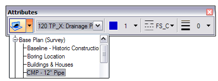
To ensure correct element symbology while placing graphics in a design file, DelDOT has defined standard element symbology settings. These settings can be accessed through the Attributes toolbar as shown in figure below.
DelDOT’s standard element symbology settings are defined in a MicroStation DGN Library, DelDOT_Element_Templates_SS4.dgnlib and DelDOT_Element_Templates_SS4_Deprecated.dgnlib, which can be obtained from the DelDOT DRC website.
Level Assignments
To maintain uniformity among different drawing files, it is essential that an organized level system be utilized. MicroStation permits data to be organized in any fashion on an unlimited number of levels. DelDOT has developed a standard set of levels to be used with all design files submitted to or exchanged with the Department.
The Department has expanded its level system from the previous 1-63 system to a virtually limitless level system. All use of the old 1-63 level system should be discontinued.
As mentioned in the section entitled Element Symbology, CADD users preparing contract plans for DelDOT are encouraged to use the Attributes Toolbar to insure that plan graphics are being placed with the correct element symbology, including the correct level. Placing plan graphics via the drop down menu system found in the DelDOT Menu Bar also insures the correct placement of element symbology.
DelDOT’s standard levels are defined in two MicroStation DGN Libraries, DelDOT_Levels_SS4.dgnlib and DelDOT_Levels_SS4_Deprecated.dgnlib, which can be obtained from the DelDOT DRC website. There is only one MicroStation DGN Library for MicroStation CONNECT, deldot_levels.dgnlib available from the same website.
Note: The MicroStation configuration variable MS_DGNLIBLIST is used to attach the DGNLIB file.
Users shall not create their own levels for use in any design files submitted to or exchanged with DelDOT. If you would like to request additional levels be added to the DelDOT level structure system please contact the DelDOT CADD Support Group at DOT_CADDSupport@delaware.gov.
Cell Libraries
A cell is a complex element composed of a group of primary elements or other complex elements. Common cell types are grouped in cell libraries. For plan consistency it is advantageous to create cells for items that will be repeatedly placed in a design file. The following cell libraries are available on the DelDOT DRC website to facilitate the drawing of commonly used symbols and sheet borders as described below:
| Cell Library | Description |
|---|---|
| CP.cel | Cells used for proposed construction sheets. |
| CP_notes.cel | Cells used for proposed construction sheets. |
| CS.cel | Cells used for construction sequencing & erosion control sheets. |
| CS_notes.cel | Cells used for construction sequencing & erosion control sheets. |
| DI.cel | Cells used for public display boards. |
| DP.cel | Cells used for detour plans. |
| EC.cel | Cells used for environmental compliance sheets. |
| EC_notes.cel | Cells used for environmental compliance sheets. |
| FS.cel | Cells used for existing topographical features. |
| GG.cel | Cells used for grades and geometric sheets. |
| GG_notes.cel | Cells used for grades and geometric sheets. |
| GO.cel | |
| HV.cel | |
| HV_notes.cel | |
| LI.cel | |
| LS.cel | Cells used for landscaping sheets. |
| PE.cel | |
| PF.cel | |
| PN_notes.cel | |
| RW.cel | Cells used for right-of-way sheets. |
| RW_notes.cel | |
| SB.cel | Cells used for title sheets and overall sheet information. |
| SG.cel | Cells used for signalization sheets. |
| SH.cel | |
| SN.cel | |
| SS.cel | Cells used for signing and markings sheets. |
Most of the cells created in the DelDOT cell libraries have been created as graphic cells. The cell symbology (level, color, line style, and weight) of a graphic cell is determined when it is created. When graphic cells are placed, they are level-independent, i.e., they keep the settings that were active when they were created. A few cells have been created as point cells where appropriate. A point cell takes on the active symbology set in the design file at the time it is placed. An example of a point cell is the line terminator arrow head (FS_ARO).
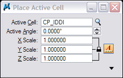
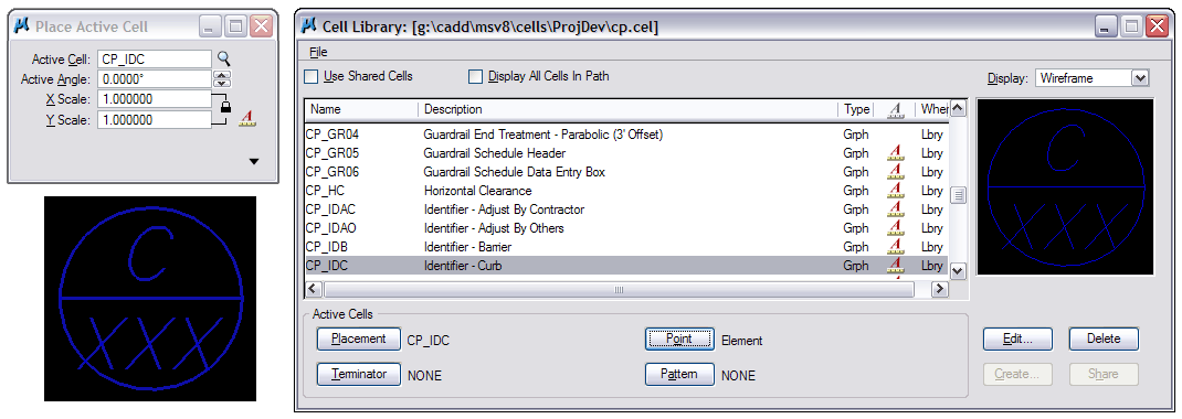
Many of the cells in the DelDOT cell libraries have been defined using real world dimensions (i.e. barriers, curbs, guardrails, etc.). These cells should always be placed in the design file with a scale factor of 1. Real world dimension cells are easily identified in the cell library palette by the missing Annotation Scale (“A”) icon, such as in the case for cell CP_GR04: Guardrail End Treatment – Parabolic in Figure 8.
Other cells have been defined to represent the location of a plan view feature but not the actual size of the element (i.e. utility poles, mail boxes, valves, etc.). These cells are intended to be placed in the design file using the annotation/drawing scale factor which is equivalent to the intended plan sheet plotting scale.
There are occasions where it may be necessary to override a cell’s symbology, such as the cell’s level at time of placement. An example of this would be the placement of maintenance of traffic (MOT) items on specific MOT Phase levels (Ex. Phase 1, Phase 2, etc.).
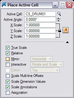
In this case cells are to be placed with the Relative toggle turned on as shown in the dialog below. It is essential to verify that the intended level is the active level prior to the cell’s placement.
Models
Each MicroStation XM design file is composed of one or more Models. A model is a separate drawing area with its own set of view parameters, reference file attachments, etc., stored within a single MicroStation Design file. Models can be either two-dimensional (2D) or three-dimensional (3D).
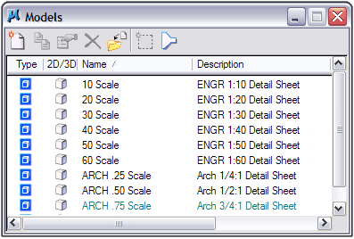
The most common use of models is in the creation of detail sheets. Construction details can be drawn at true scale in the scale specific model (Ex: 20 Scale), and annotated at that specific drawing or annotation scale. The multi-scale details can then be referenced into a single scale master detail sheet for printing purposes.
When multi-scale reference files are attached, users must be sure to select the appropriately scaled model within the referenced design file. As references are attached to design file, they are attached to active model within the active design file.
Strip Design Files
Design files that encompass the entire limits of a project are referred to as strip design files and are used to create existing and proposed plan view graphics that will encompass the entire length of the project for both Roadway and Bridge projects. All strip file information shall be created as individual MicroStation design files and not combined into one design file as separate design models.
The location and dimensions of all plan view strip file information shall be drawn using real world dimensions at 1:1 scale; however, cell scales and text annotation should be set for the intended plotting scale of the plan as previously detailed in this chapter.
For Roadway projects, a minimum of four (4) plan view strip design files are required:
- FS.dgn – this file contains the existing topographical ground survey information.
- RW.dgn – this file contains the existing and proposed right-of-way information.
- AL.dgn – this file contains the construction alignment information.
- PC.dgn – this file contains the proposed construction information.
| Strip Design File Name | Strip Design File Description / Contents |
|---|---|
| AL00.dgn | Construction alignment layout information. |
| CS00.dgn | Construction sequence and phasing information. |
| FS00.dgn | Field survey / existing topography information. |
| HY00.dgn | Hydrology and drainage information. |
| LI00.dgn | Lighting information. |
| PC00.dgn | Proposed construction information. |
| RW00.dgn | Right-of-way information, existing and proposed. |
| SF00.dgn | Shape file for shading. |
| UT00.dgn | Utilities information, existing and proposed. |
A strip design file is also used for profiles and cross section graphics. Unlike plan view strip design files, profile and cross section strip design files shall contain both existing and proposed information in one file.
The profile strip design file may be used to display all of the profiles for the entire project in one file. It is not necessary to create separate profile strip design files for each alignment. Profiles should always be displayed in their own strip design file and never combined with any other strip design file (Ex: Never display profiles in the proposed construction strip design file).
The cross section strip file may be used to display all of the cross sections for the entire project in one file. It is not necessary to create separate cross section strip design files for each alignment. Cross sections should always be displayed in their own strip design file and never combined with any other strip design file.
Chapter 4 - DelDOT Menu Bar
To ensure consistency and uniformity while placing graphics into a MicroStation design file, DelDOT has developed a custom menu bar that makes use of the BARMENU MDL application. This custom menu bar is referred to as the DelDOT Menu Bar and is generally used to define the standard symbology (level, color, line style and weight) for all elements contained within a file.
Menu Layout
The DelDOT Menu Bar contains a minimum of three drop down menus. The Plan Type, DelDOT Common and Info menus are static menus and contain the same content regardless of the plan sheet type that has been selected.
The fourth drop down menu is discipline or sheet specific and is either populated automatically upon opening a design file, provided the design file follows the DelDOT naming convention established earlier in this manual, or set manually by the user as needed. (Ex: TS.dgn will add the Typical Sections menus and tools to the DelDOT Menu Bar as shown below.)
Plan Type
As discussed in Chapter Two – Directory and File Naming, DelDOT strongly encourages the use of the two character design file naming convention. The DelDOT Menu Bar application utilizes this file naming convention to automatically populate the information in the discipline specific drop down menus.
It is also possible to manually select a discipline specific menu from the Plan Type drop down menu. A listing of the plan types and descriptions is provided below. Bridge specific sheet types have been grouped together under the Bridge Specific Sheets category in the Plan Type drop down menu.
| Plan Type Abbreviation | Plan Type Description |
|---|---|
| AB | Bridge Abutment Details |
| AR | Arch Bridge Details |
| AS | Bridge Approach Slab Details |
| BD | Bridge Bearing Details |
| BM | Bridge Beam Details |
| BO | Boring Log |
| BR | Reinforcing Bar Summary |
| CO | Bridge Composite Details |
| CP | Construction Plans |
| CS | Construction Sequence/Phasing |
| CT | Bridge Camber Table |
| CU | Culvert Details |
| DI | Display / Presentation |
| DK | Bridge Deck Plan |
| DP | Detour Plan |
| DT | Miscellaneous Details |
| EC | Environmental Compliance |
| EX | Expansion Joint |
| FD | Finished Bridge Deck Elevations |
| FR | Bridge Framing Plan |
| FS | Field Survey/Existing Topography |
| FT | Bridge Footing Plan |
| GG | Grades & Geometric Plans |
| HV | Horizontal and Vertical Control |
| HW | Bridge Headwall Details |
| IS | Index Sheet |
| LI | Lighting Plans |
| LS | Landscaping Plans |
| MD | Model File |
| PA | Bridge Parapet Details |
| PC | Proposed Construction |
| PE | Bridge Plan and Elevation |
| PF | Profiles |
| PL | Bridge Pile Details |
| PN | General & Project Notes |
| PR | Bridge Pier Details |
| RA | Bridge Rail Details |
| RB | Right-of-Way Metes and Bounds |
| RD | Retaining Wall Details |
| RF | Bridge Rigid Frame Details |
| RH | Bridge Rehabilitation Details |
| RM | Right-of-Way Mosaic |
| RT | Right-of-Way Tabulation |
| RW | Right of Way |
| SB | Project Sheet Border |
| SD | Standard Construction Details |
| SF | Shape / Shading File |
| SG | Signalization Plan |
| SH | Bridge Sheet Pile Details |
| SP | Bridge Slope Protection Details |
| SR | Structure Removal |
| SS | Signing, Signing and Conduit Plans |
| ST | Bridge Special Structure Details |
| SW | Storm Water Management |
| TC | Construction Title Sheet |
| TD | Bridge Timber Structure Details |
| TR | Right-of-Way Title Sheet |
| TS | Typical Sections |
| UT | Utilities |
| WD | Bridge Wick Drain Layout Sheet |
| WW | Bridge Wingwall Details |
| XS | Cross Sections |
DelDOT Common Menu
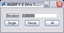
Set Element Elevation - this tool provides the user with the ability to move a single element, elements contained by a fence or all elements within the design file to a user defined elevation.
Load ModZ - loads the MODIFY Z application for the first time during the MicroStation session.
Unload ModZ - unloads or closes the MODIFY Z application from MicroStation. Note: Dismissing the dialog box by selecting the close icon (red “X”), does not unload this application. To reuse the MODIFY Z application after dismissing the dialog box the user must choose the Unload ModZ tool from the menu.
Area Tools – this menu item displays the Area Tools palette which contains the following tools:
- Measure Area and Place Area Text
- Place Area with Text
- Area Calculator
- Area Tool Parameters
Civil Tools - this menu item displays the Civil/Site Tools palette which contains the following tools:
- Place Contour
- Label Contour
- Place Breakline
- Place Coordinate
- Modify Contour
- Set Element Elevation
- Place Spot Elevation
- Place Composite Curve
- Civil Tools Settings
Info Snap - this menu allows the user to either turn on or turn off the MicroStation InfoSnap settings.
Pipe Cut Symbol - this menu allows the user to either turn on or turn off the pipe cut symbol used when creating details.
Place Steel Section - this menu allows the user to select steel section for insertion into drawing or detail. Shapes included are W-Shape, S-Shape, HP-Shape, M-Shape, Structural Tubing, etc.
Start InRoads - this menu allows the user to launch InRoads, InRoads Site, InRoads Storm & Sanitary or InRoads Survey directly from within an active MicroStation session.
Start AutoTrack - this menu allows the user to launch AutoTrack directly from within an active MicroStation session.
Set Model Scale/Working Units - this item activates the Drawing Scale palette where the user can set the Working Units (Master & Sub units) and the active Model or Drawing Scale. The Annotation Scale Lock can be toggled on or off from this palette as well.
Coordinate Readout - this item activates the Coordinate Readout palette where the user can set the Coordinate Format, Coordinate Accuracy, Angle Format, Angle Mode and Angle Accuracy.
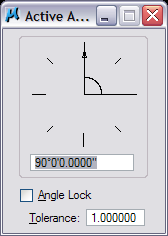
Set Active Angle - this item allows the user to set the active angle within the design file by one of three methods: By 2 Points, By 3 Points or By Dialog.
Set Active Elevation = 0 - this menu item sets the view’s active depth to an elevation of 0.0000. This menu item performs the same function as typing “az=0” into the MicroStation Key-In line.
Reset View Depth - this menu item sets the view display depth to -10000, 10000. This menu item performs the same function as typing “dp=-10000,10000” into the MicroStation Key-In line.
Level Display - this menu item activates the Level Display palette. This menu item performs the same function as selecting the CTRL+E shortcut
Change Level - this menu item activates the Change Level palette which enables the user to either turn a level off or isolate the level so it is the only level on, by selecting an element on the affected level.
All Levels ON – this menu item allows the user to turn on all of the MicroStation design file levels for All Views or a specific view. This menu item performs the same function as right-clicking in the Level Display window and selecting All On from the pop-up palette.
All Levels OFF - this menu item allows the user to turn off all of the MicroStation design file levels for All Views or a specific view. This menu item performs the same function as right-clicking in the Level Display window and selecting All Off from the pop-up palette.
View Attributes - this menu item allows the user to toggle on or off the following view attribute settings:
- Area Fill
- Data Fields
- Dimensions
- Dynamics
- Fast Cells
- Fast Curves
- Fast Font
- Grid
- Level Symbology
- Line Weight
- Pattern
- Text
- Text Nodes
Set Highlight - this menu item allows the user to select from one of the eight element selection highlight colors.
Change Element Direction - this menu item allows the user to reverse the direction of an element from that in which it was originally drawn.
Shift LineStyle - this menu item allows the user to shift or slide the linestyle elements along the length of the linear element.
AutoLocate Toggle - this menu item allows the user to toggle on or off the AccuSnap AutoLocate feature. Using the AutoLocate feature allows the user to hover over an element to highlight or select the element without having to actually click-select the element.
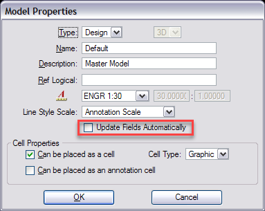
Update Fields - this menu item allows the user to update the various fields within a MicroStation design file on demand, instead of keeping the Update Fields Automatically model property toggled on. Leaving this field toggled on will increase the time it takes to open up the design file and is not recommended.
Plan Type Specific Menus
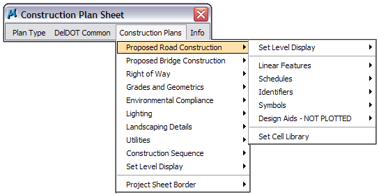
As mentioned under the Menu Layout section of this chapter, depending on the name of the active design file, the DelDOT Menu Bar will automatically populate a drop down menu for the discipline specific sheet type. This discipline specific drop down menu contains tools and settings that were developed for that particular sheet type to improve consistency and uniformity between plan sets.
The following component groups are found in most of the discipline specific menus:
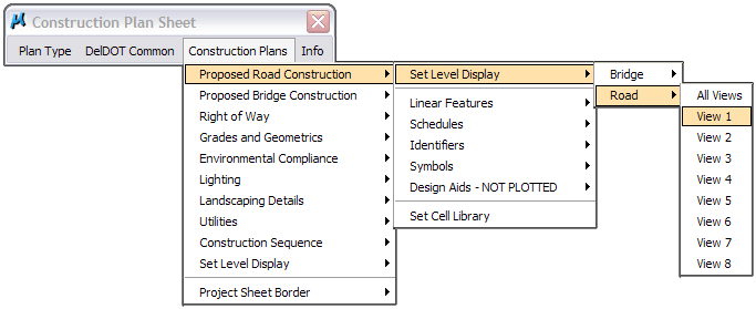
Set Level Display - this menu item allows the user to set the level display for either an individual view or all of the views. The view level settings are determined by a VBA macro that utilizes the deldot_levels.xls file to determine which levels should be on or off for a particular sheet type.
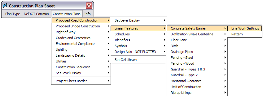
Linear Features - this menu item contains element symbology settings (level, color, style and weight) for most of the graphical elements that are placed within a design file. The settings under these menu items are determined by the MicroStation Active Element Templates, and will not work correctly if the deldot_templates.dgnlib file has not been added to the MicroStation configuration.
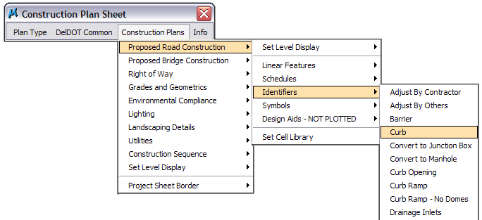
Identifiers - this menu item contains a listing of all of the identifiers that are used for a particular sheet type.
Symbols - this menu item contains a listing of all of the symbols/cells that are used for a particular sheet type.
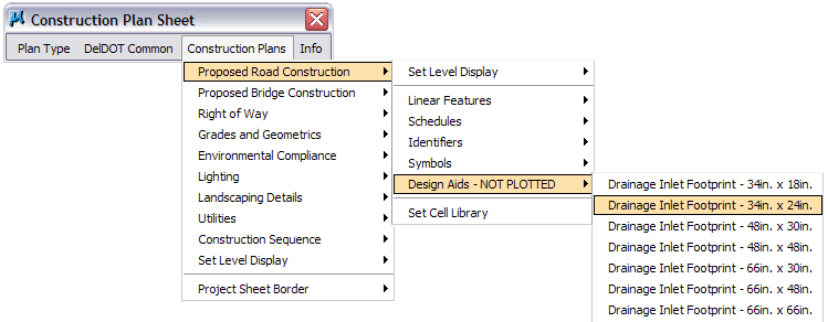
Design Aids - this menu item contains a listing of design aids that may be used for a particular sheet type.
Info
DelDOT Design Resource Center - this menu item links directly to the DelDOT’s Design Resource Center (DelDOT DRC) website home page.
DelDOT CADD Standards Manual - this menu item links directly to the most current version of the DelDOT’s CADD Standards Manual.
DelDOT Levels - this menu item links directly to the deldot_levels.xls workbook where users can view the current level assignments and level display settings.
Bentley Communities - this menu item links directly to the Bentley BE Communities website home page where users can find additional help, discussion forums, and tips for all of the Bentley products.
Bentley Discussion Groups - this menu item links directly to the archived Bentley Discussion Groups website where users can perform searches for additional help on all of the Bentley products.
Bentley ETS – Online Training - this menu item links directly to the Bentley Learn Server website home page where users can search through the OnDemand eLearning Courses for training materials on all of the Bentley products. A user ID and password is required to access the training information.
Bentley Online Feature Tips - this menu item links directly to the Bentley Learn Server Feature Tips and Product Demonstrations home page where users can view Feature Tips for all of the Bentley Products.
Bentley Software Documentation - this menu item links directly to the Bentley Public Documentation Archive where the user can view the user’s manuals, training guides and references for all of the Bentley products.
Chapter 5 - Reference Files
Reference files are used to display or reference the contents of one or more MicroStation design files into the active design file.
The most common use of reference files is the display of strip design files such as the field survey file (fs00.dgn) into the construction plan sheet design files (cp01.dgn) to generate the various plan sheets used on a typical DelDOT project.
Reference files are also used to display the entire contents of one strip design file into another strip design file to facilitate the design process (Ex: The entire contents of the field survey design file (fs00.dgn) is referenced into the proposed construction design file (pc00.dgn) so that the entire corridor can be viewed at one time during the design process).
Saving Relative Path
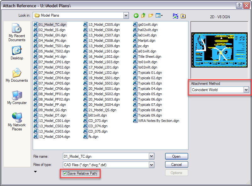
When attaching reference files to active design files it is recommended that the user enable the Save Relative Path feature check box. This feature stores the directory location of the reference file relative to the directory of the active design file, thereby promoting the portability of the project directory.
Note: The Save Relative Path setting has replaced the Save Full Path feature from previous version of MicroStation.
Coincident World
When attaching reference files to active design files it is recommended that the user select the Coincident World attachment method to insure that the global origins of referenced files are adjusted to the global origin of the active file, when attached. See Figure 10 for the location of the Attachment Method drop-down list.
True Scale
When attaching reference files to active design files it is recommended that the user enable the True Scale check box (See Figure 15). This feature adjusts the reference files Units of Resolution if they are different from the active design file.
2D and 3D Design File References
MicroStation XM allows cross referencing of 2D files and 3D files into one another. In previous versions of MicroStation this feature was not available, so 3D files were copied and converted to 2D files so references could be made to 2D files. This is no longer required, so 3D files should not be copied and converted to 2D, thus eliminating duplicate information.
Chapter 6 - Raster Manager
Raster files are used to display the contents of one or more image files into the active design file. MicroStation supports the attachment of several types of image files, the most common being the .jpg, .tiff, and .img raster image types.
The most common use of raster files is the display of aerial imagery into design files as a background for planning, design and presentation purposes. It is also possible to attach scanned paper archived plan sheets into the active design files through the use of the Raster Manager.
Aerial Imagery
DelDOT maintains copies of aerial imagery files for the entire State of Delaware on the OIT Server located at \\dotsan02\apps\orthophotography. This server contains imagery files for the following years and file types:
- 1937 – Grayscale images.
- 1992 – Grayscale and infrared images.
- 1997 – Grayscale images.
- 2002 – High and low resolution grayscale and infrared files.
- 2007 – High resolution color files.
Place Interactively
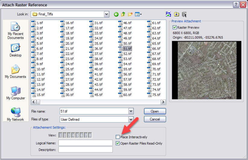
In most instances when attaching the aerial imagery files mentioned above to active design files it is recommended that the user leave the Place Interactively attachment method unselected to insure that the aerial file maintains the proper geographical position.
Attaching Aerial Imagery for Presentation Purposes
In cases where the aerial imagery files located at \\dotsan02\apps\orthophotography are going to be used for presentation purposes it is recommended that the user follow the workflow list below when making the aerial file attachment.
Note: When attaching 1 to 2 image files to MicroStation, an Image Quality setting of “12 – Maximum” is recommended when converting the image files to .jpg format. If more than 2 image files are to be attached, the Image Quality may be reduced to improve the overall speed of MicroStation.
- Open the aerial file using Adobe Photoshop and convert the file to a .jpg format file. This conversion will reduce the image file from 250MB to approximately 35MB and will improve the overall speed of MicroStation when the file is attached.
- As part of the conversion process listed in step 1, the geographical location of the aerial image file has been modified. To insure proper placement of the converted file at time of attachment it is recommended that the user attach the original .tif file located in \\dotsan02\apps\orthophotography to establish the correct location of the image file.
- Once the original image file has been attached, and the true geographical location has been established, the converted file can be attached. The key to insuring the converted file is attached correctly is selecting the Place Interactively attachment method at time of attachment. With this toggle turned on the user will be prompted to “Enter Origin” and “Enter Corner” for the raster attachment. At these prompts, tentative to one corner of the origin file boundary and then the opposite corner to set the limits.
Following this workflow will improve the speed and efficiency of MicroStation as well as allow for the use of the Active Element Transparency, which will not work correctly with large raster file attachments.
Chapter 7 - Plotting
One of the primary reasons for following the requirements listed in the CADD Standards Manual is to enable the creation of uniform plot sets. Inevitably when plotting issues occur it is because the requirements listed in this manual were not followed. Therefore, strict adherence to these requirements must be maintained to insure consistent and uniform plots.
Plotting Sizes
DelDOT produces plan sets in the following sizes:
- Full Size: 34” x 22”
- Half-Size: 17” x 11”
Plotting Software & Hardware
As of March of 2018, DelDOT uses the following software and hardware packages to generate full size and half-size plan sets:
- Software Application: Bentley InterPLOT
- Plotter: KIP 7970 and the Océ ColorWave 500
Line Widths
DelDOT uses a design script that is applied to the graphical elements when the design file is plotted. This can be thought of as a type of filter. The design script maps MicroStation line weights to specific pen sizes or thicknesses and apply these thicknesses to the elements as they are plotted.
An example would be mapping all elements whose weight value is set to 0 to a thickness of 0.005-inch and all elements whose weight value is set to 1 to a thickness of 0.013-inch to differentiate the design file element’s weights on the plotted sheet.
Line thicknesses should be plotted as shown in the following table.
| Element Weight | Thickness (Approximate Inches) |
|---|---|
| WT = 0 | 0.005” |
| WT = 1 | 0.013” |
| WT = 2 | 0.018” |
| WT = 3 | 0.023” |
| WT = 4 | 0.028” |
| WT = 5 | 0.033” |
| WT = 6 | 0.038” |
| WT = 7 | 0.043” |
| WT = 8 | 0.048” |
Due to variations in plotting hardware and software outside of the Department, the thicknesses listed above may be modified to match our standards.
Design Scripts (.dscript)
DelDOT uses a design script during the plotting process that has been developed for the various types of sheets the user may encounter on each project, and is listed along with the corresponding IPARM File (.i) under the Design File & IPARM File (.i) Categories section of Chapter 2.
IPlot Settings Files (.set)
IPlot settings files are being introduced as an aid to automating the plotting process. The IPlot setting files are ASCII text files that contain default parameters such as the plot area, design script used, and paper size as well as level display. IPlot settings files were developed for each type of sheet the user may encounter on a project.
These files are updated and overwritten automatically when any changes are made to levels.
The following IPlot settings files are available on the DelDOT ProjectWise system.
| IPlot Settings File | IPlot Settings File Use |
|---|---|
| AB.set | Plotting of Bridge Abutment Details |
| AR.set | Plotting of Arch Bridge Details |
| AS.set | Plotting of Bridge Approach Slab Details |
| BB.set | Plotting of Bridge Bearing Details |
| BD.set | Plotting of Bridge Details |
| BM.set | Plotting of Bridge Beam Details |
| BO.set | Plotting of Boring Log |
| BR.set | Plotting of Reinforcing Bar Summary |
| CO.set | Plotting of Bridge Composite Details |
| CPB.set | Plotting of Construction Plan Sheet (Bridge) |
| CPR.set | Plotting of Construction Plan Sheet (Road) |
| CS.set | Plotting of Construction Phasing, MOT & Erosion Control sheets. |
| CSG.set | Plotting of General Construction Sequence |
| CSR01.set | Plotting of Construction Sequence (Road Phase 1) |
| CSR02.set | Plotting of Construction Sequence (Road Phase 2) |
| CSR03.set | Plotting of Construction Sequence (Road Phase 3) |
| CSR04.set | Plotting of Construction Sequence (Road Phase 4) |
| CSR05.set | Plotting of Construction Sequence (Road Phase 5) |
| CSR06.set | Plotting of Construction Sequence (Road Phase 6) |
| CSR07.set | Plotting of Construction Sequence (Road Phase 7) |
| CSR08.set | Plotting of Construction Sequence (Road Phase 8) |
| CSR09.set | Plotting of Construction Sequence (Road Phase 9) |
| CSR10.set | Plotting of Construction Sequence (Road Phase 10) |
| CSB01.set | Plotting of Construction Sequence (Bridge Phase 1) |
| CSB02.set | Plotting of Construction Sequence (Bridge Phase 2) |
| CSB03.set | Plotting of Construction Sequence (Bridge Phase 3) |
| CSB04.set | Plotting of Construction Sequence (Bridge Phase 4) |
| CSB05.set | Plotting of Construction Sequence (Bridge Phase 5) |
| CSB06.set | Plotting of Construction Sequence (Bridge Phase 6) |
| CSB07.set | Plotting of Construction Sequence (Bridge Phase 7) |
| CSB08.set | Plotting of Construction Sequence (Bridge Phase 8) |
| CSB09.set | Plotting of Construction Sequence (Bridge Phase 9) |
| CSB10.set | Plotting of Construction Sequence (Bridge Phase 10) |
| CT.set | Plotting of Bridge Camber Table |
| CU.set | Plotting of Culvert Details |
| DI.set | Plotting of Display / Presentation |
| DK.set | Plotting of Bridge Deck Plan |
| DP.set | Plotting of Detour Plan |
| DT.set | Plotting of Misc. Details |
| EC.set | Plotting of Environmental Compliance |
| EX.set | Plotting of Expansion Joint |
| FD.set | Plotting of Finished Bridge Deck Elevations |
| FR.set | Plotting of Bridge Framing Plan |
| FS.set | Plotting of Field Survey/Existing Topography |
| FT.set | Plotting of Bridge Footing Plan |
| GG.set | Plotting of Grades and Geometrics Strip File |
| HV.set | Plotting of Horizontal and Vertical Control |
| HW.set | Plotting of Bridge Headwall Details |
| IS.set | Plotting of Index Sheet |
| LG.set | Plotting of Legend Sheet |
| LI.set | Plotting of Lighting Strip File |
| LS.set | Plotting of Landscaping Details/Strip File |
| MD.set | Plotting of Model File |
| MP.set | Plotting of Mapping File |
| PA.set | Plotting of Bridge Parapet Details |
| PC.set | Plotting of Proposed Construction Strip File |
| PE.set | Plotting of Bridge Plan and Elevation |
| PF.set | Plotting of Profiles |
| PL.set | Plotting of Bridge Pile Details |
| PN.set | Plotting of General and Project Notes |
| PR.set | Plotting of Bridge Pier Details |
| QS.set | Plotting of Quantity Summary |
| RA.set | Plotting of Bridge Rail Details |
| RB.set | Plotting of Right-of-Way Metes and Bounds |
| RD.set | Plotting of Retaining Wall Details |
| RF.set | Plotting of Bridge Rigid Frame Details |
| RH.set | Plotting of Bridge Rehabilitation Details |
| RM.set | Plotting of Right-of-Way Mosaic |
| RT.set | Plotting of Right-of-Way Tabulation |
| RWB.set | Plotting of Right-of-Way Strip File (Bridge) |
| RWR.set | Plotting of Right-of-Way Strip File (Road) |
| SB.set | Plotting of Project Sheet Border |
| SD.set | Plotting of Standard Construction Details |
| SF.set | Plotting of Shape File (Shading) |
| SG.set | Plotting of Signalization Plan |
| SH.set | Plotting of Bridge Sheetpile Details |
| SP.set | Plotting of Bridge Slope Protection Details |
| SR.set | Plotting of Structure Removal Plan |
| SS.set | Plotting of Signing Striping and Conduit Strip File |
| ST.set | Plotting of Bridge Special Structure Plans |
| SW.set | Plotting of StormWater Management |
| TC.set | Plotting of Construction Title Sheet |
| TD.set | Plotting of Bridge Timber Structure Details |
| TI.set | Plotting of Title Sheet - General |
| TR.set | Plotting of Right-of-Way Title Sheet |
| TS.set | Plotting of Typical Sections |
| UT.set | Plotting of Utility Strip File |
| WD.set | Plotting of Bridge Wick Drain Layout Sheet |
| WW.set | Plotting of Bridge Wingwall Details |
| XS.set | Plotting of Cross Sections |
IPARM File (.i) Attributes
To ensure consistent plotting output, the following MicroStation View Attributes should always be turned on when creating IParm files: Fill, Line Styles, Line Weights, Patterns and Text.
The following MicroStation View Attributes should always be turned off when creating IParm files: Data Fields and Text Nodes.
IParm files are created with specific levels turned on and off to correctly generate the final output (Plot, PDF, etc.). Due to the limitless number of available levels in MicroStation and the dynamic nature of the display of each of these levels, DelDOT has opted to use the DelDOT Menu Bar to correctly handle the display of levels for each sheet type.
As mentioned in Chapter 4 – DelDOT Menu Bar, the settings contained in the DelDOT Menu Bar for each of the various sheet types is determined by the data contained within the deldot_levels_SS4_V2.xlsm (V8i) or DelDOT_Levels.xls (CONNECT) file which is available on the DelDOT ProjectWise system.
PDF File Requirements
DelDOT requires that all contract plan sheet files generated for submission to the Department, whether for plotting or viewing purposes, be 600 dpi georeferenced vector images. To ensure consistent plotting quality, DelDOT will not accept PDF files that utilize different dots per inch (dpi) settings.
