Existing ROW Mosaic Creation - RW2201
From DelDOT CADD Wiki
Introduction
The following workflow shall be used for the creation of the Existing RW Mosaic for DelDOT projects. This workflow utilizes MSCE, ORD and PW and is only valid for these applications. Older projects not utilizing these applications, such as those still using InRoads v8i, should utilize with the previously established workflows for those applications.
It is the responsibility of the EOR to obtain the necessary information to establish the existing RW Mosaic. For internal projects, the EOR shall utilize the forms on the DRC to obtain the appropriate deeds and/or title searches.
Through the following workflow, the user will:
- Upload a single PDF file for each parcel (Single Parcel PDF).
- Enter parcel attributes for each Single Parcel PDF.
- Generate unadjusted existing parcel boundaries in ORD and save as an XML file.
- Adjust the existing parcel boundaries to the final orientation.
- Associate the appropriate Parcel ID to each parcel to link parcel attributes.
- Save the adjusted existing parcel boundaries as XML files.
Creation of the Existing RW Mosaic
1. Enter Property information in DelDOT PW System
1.1 Upload Single Parcel PDFs.
All parcel information (deeds, Microfilms, etc...) shall be combined into one single PDF file per parcel and named in accordance with the Team Support Manual (soon to be published).
1.1.1 Inside of File Explorer, select all Single Parcel PDFs to be uploaded to PW and drag and drop into the 280_EXISTING_PROPERTY_RIGHTS folder inside of PW.
Important Note: For Consultants, this data must be uploaded into the DelDOT side 280_EXISTING_PROPERTY_RIGHTS. In the example shown below, this would be the T202207101 folder, not the T202207101_TYL or T202207101_WM.
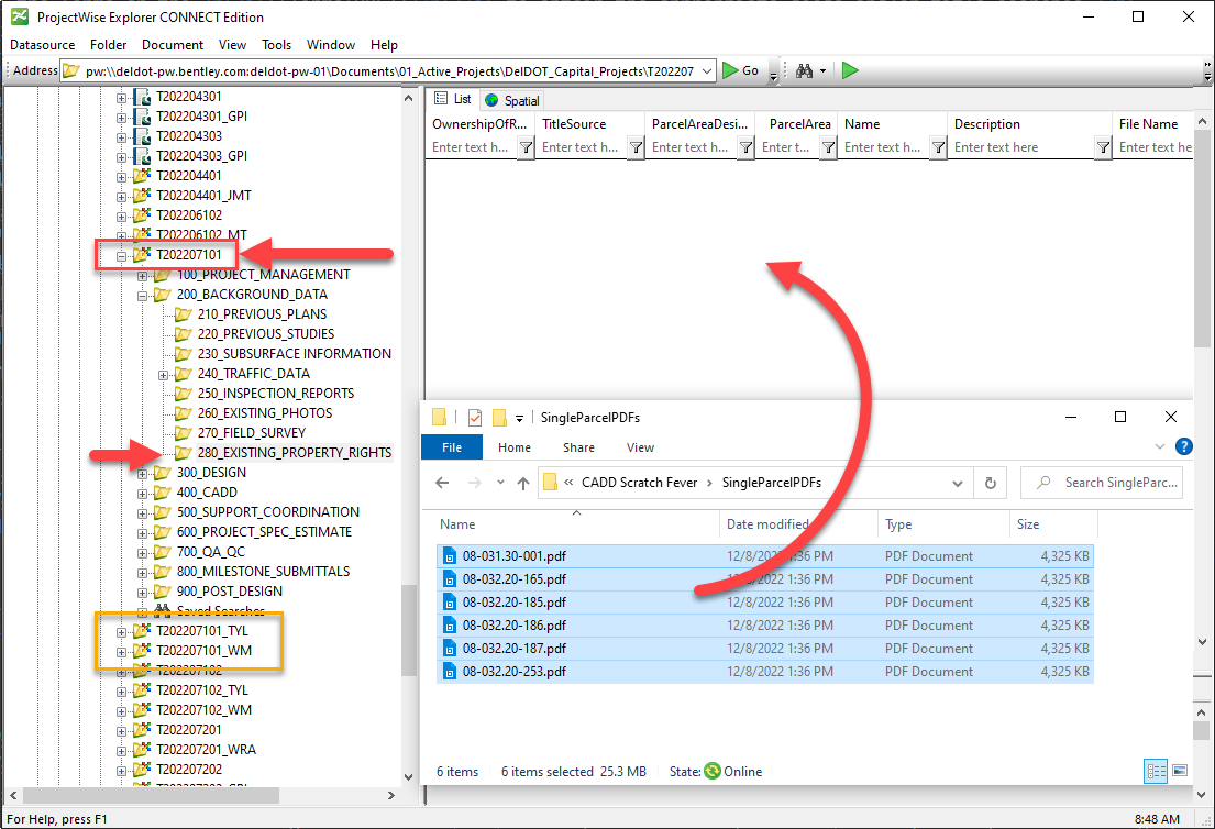
Note: While other files are allowed in 280_EXISTING_PROPERTY_RIGHTS, the system will only look at PDFs when creating the Linking file. Any miscellaneous PDFs in this folder will cause issues when generating the Linking file.
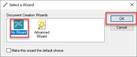
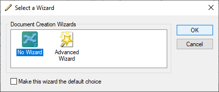
1.1.2 Select No Wizard and hit OK.
1.2 Entering Existing Property Information
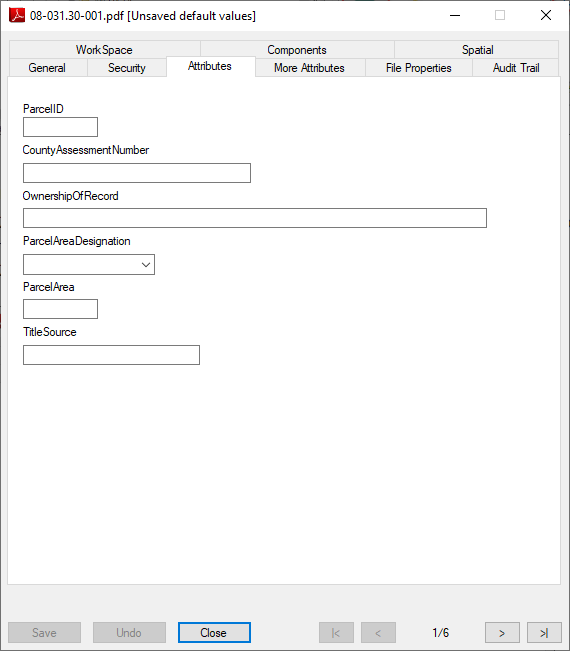
1.2.1 Select a Single Parcel PDF and press the Space bar on your keyboard to bring up the file properties.
Important Note: You should only enter the Attribute data for the Single Parcel PDF.
1.2.2 Select the Attributes tab at the top.
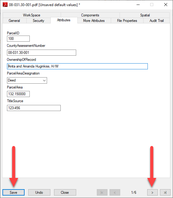
Important Note: A Parcel ID must to be assigned by the EOR to each parcel at this time as it will be the way MSCE, ORD and PW cross reference all Parcel and Acquisition data moving forward. The following should kept in mind when assigning the Parcel IDs:
- Each Parcel must be assigned a unique integer based Parcel ID.
-
Parcel IDs should be assigned sequentially based on their geographical location on the Project.
For example, begin with 1 in the south/west of the project and go up sequentially toward the north/east of the project. - Once assigned, a Parcel ID cannot be changed so care should be taken in how the Parcel IDs are initially assigned.
1.2.3 Enter the appropriate attribute data for each field of the parcel, in accordance with the TS Manual. Click the Save button and press the Next button.
1.2.4 If the file named Project_Parcels.xlsx exists, delete it from the 280_EXISTING_PROPERTY_RIGHTS folder. If you do not see this file, you may skip this step. ! Because PW automatically generates this file, it may have generated it while you were entering the Property Information. Deleting the file will force PW to regenerate it.
1.3 Modifying Existing Property Information
Important note: ProjectWise automatically creates a file named Project_Parcels.xlsx. This file handles the necessary linking between PW and MSCE/ORD. This file takes about 30 minutes to generate.
Do not modify this file. Any manual changes to this file will be automatically overwritten when the file is regenerated.
You may need to refresh to see the changes to the Single Parcel PDFs or the Project_Parcels.xlsx. Press F5 on your keyboard to refresh, or navigate to another folder and then come back.
1.3.1 If changes are needed in the PDF file attributes, make all necessary changes to the attributes as per Section 1.2 above.
1.3.2 When the attributes are changed, you will need to delete the Project_Parcels.xlsx file so that PW automatically regenerates it.
Please note: If a file does not contain a valid Parcel ID attribute, it will be ignored when the PW automated process regenerates it.
2. Create Existing Parcels in ORD
2.1 Enter each parcel per the deed
Note: When creating the DGN for the following steps, it is recommended that you use the RM Sheet Type and the DelDOT_Seed2D_th_Bearings seed.
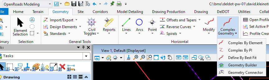
2.1.1 Open the Geometry Builder located under the OpenRoads Modeling Workflow > Geometry Tab > Horizontal Group > Complex Geometry Drop Down. ! Alternatively, you can search for it by entering Geometry Builder in the Ribbon Search Field located in the upper right corner.
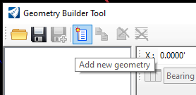
2.1.2 Inside of Geometry Builder click Add new geometry.
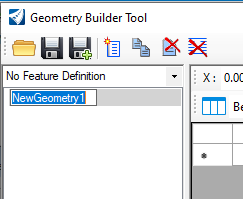
2.1.3 Select the NewGeometry entry created and rename it to the Parcel Assessment Number (PAN).
2.1.4 Select Create graphic elements.
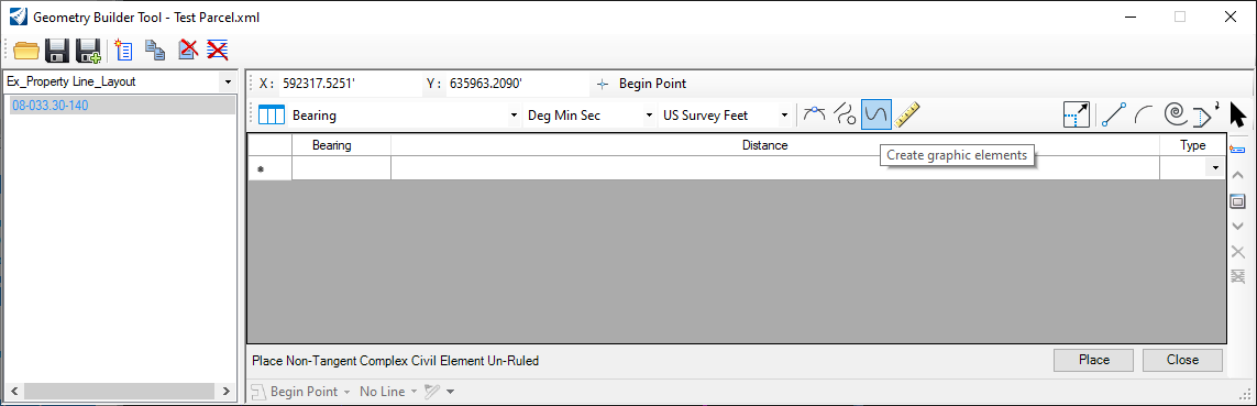
2.1.5 Click the Select begin point button and choose an approximate location in the design file where the parcel will be drawn.
Note: This will be adjusted in Section 3 of this wiki.
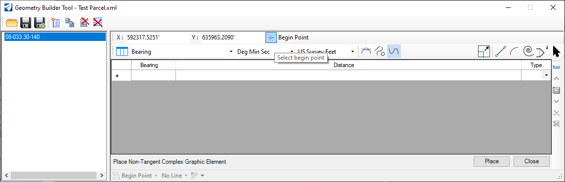
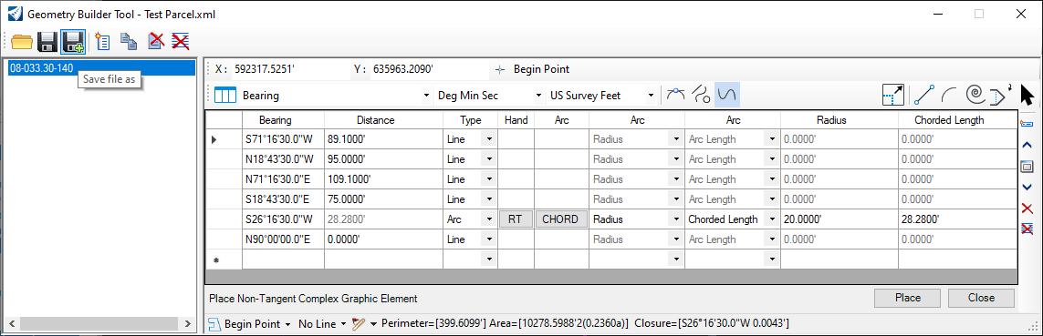
2.1.6 By default, Geometry Builder sets the Type to Line. To enter a Line, enter in the Bearing per the deed in the Bearing column and hit enter on your keyboard to move to the Distance column.
Note: To enter South 71 degrees 16 minutes 30 seconds West you would type it in as s71 [space] 16 [space] 30w.
2.1.7 Enter the Distance and hit enter on your keyboard to move to the next row.
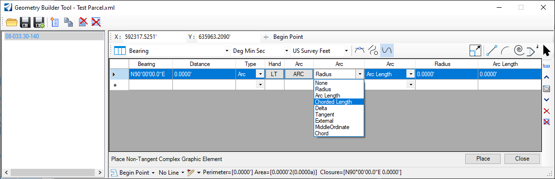
2.1.8 To enter a type of segment other than a line, select the appropriate segment type from the dropdown.
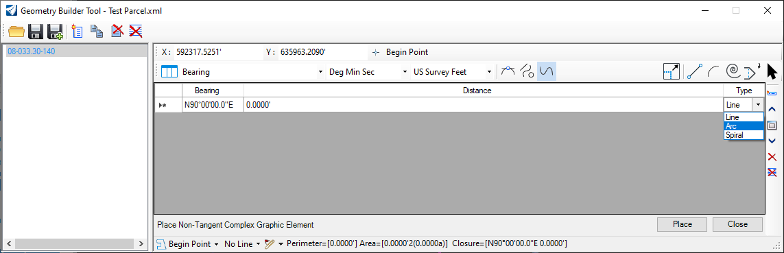
2.1.9 Change the options for the input as necessary, fill out the remaining fields and hit Enter on your keyboard to go to the next line.
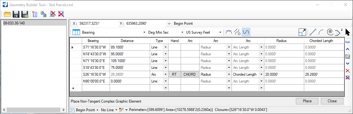
2.1.10 Continue entering rows as necessary, when finished entering in all of the metes and bounds for the parcel click Place.
Note: You can check the Closure direction and distance along with various other information along the bottom of the Geometry Builder window.
2.2 Save Each Parcel
The output file format from Geometry Builder is XML. The XML can store a single geometry or multiple geometries. The following steps will outline saving each geometry to a single XML file and store it in the appropriate folder on PW.
2.2.1 In Geometry Builder, click the Save file as button.
2.2.2 Choose No Wizard and hit OK.
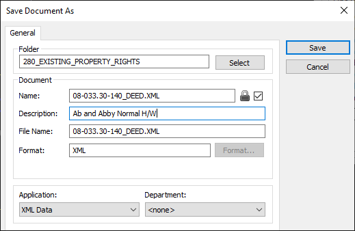
2.2.3 Select the 280_EXISTING_PROPERTY_RIGHTS folder and select OK.
2.2.4 In the Name field, enter the name per the following format and click Save:
[PAN]_DEED.XML
(PAN = Parcel Assessment Number)
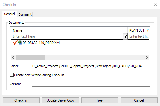
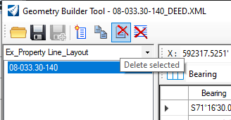
2.2.5 Click Check In.
2.2.6 Click Delete selected and go back to step 2.1.2 for each parcel on the project.
Alternatively, you can rename the geometry instead of deleting and creating a new one. Make sure to delete all entries within the geometry.
3. Adjust and Associate Parcel ID
It is the responsibility of the EOR to do their due diligence to assure that the parcels are stitched together to create an accurate mosaic according to all current regulations. The EOR is to provide written documentation detailing all assumptions and adjustments that were made during this process.
It is recommended that the EOR make notes on the RW_X_Design Notes level document assumptions and adjustments that were made to stitch together the mosaic.
3.1 Adjust Parcels in ORD
3.1.1 Select the parcel shape to be adjusted in ORD.
3.1.2 Move and/or rotate the parcel to the appropriate location.
3.1.3 If necessary, use the Drop Element tool and adjust individual segments of the parcel.
Note: The parcel should be a closed Complex Shape. Use the Create Complex Shape tool to rejoin the parcel when finished with the adjustments.
3.2 Associate Parcel ID
By associating a Parcel ID to each of the existing parcels, MSCE/ORD will be able to pull all the existing parcel attributes from PW.
3.2.1 Select the parcel in ORD.
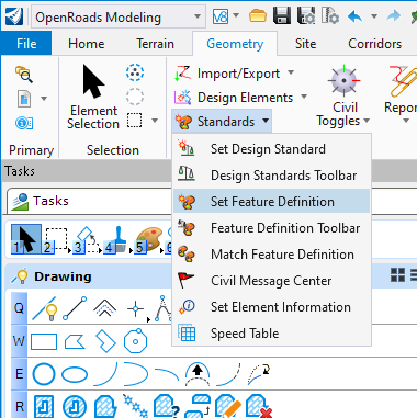
3.2.2 Set the Ex_Property Line_Layout feature with the Set Feature Definition tool located under the OpenRoads Modeling Workflow > Geometry Tab > General Tools Group > Standards Drop Down.
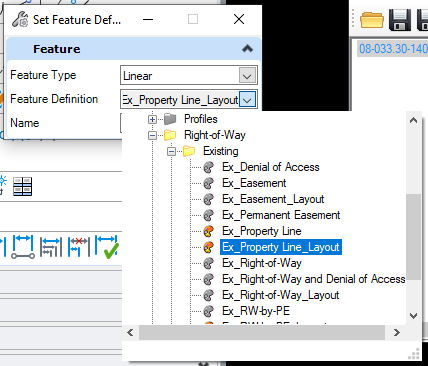
3.2.3 Click the drop down next to Feature Definition and select Linear > Right-of-Way > Existing > Ex_Property Line_Layout.
3.2.4 Select the parcel and Left-Click to accept.
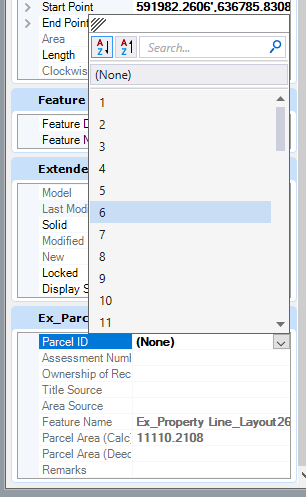
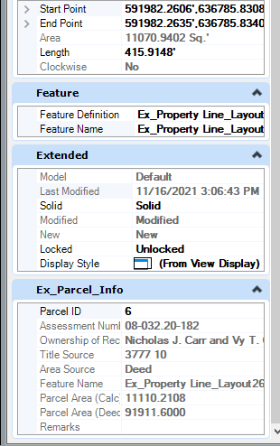
3.2.5 In the element Properties under the Ex_Parcel_Info select the Parcel ID dropdown and choose the appropriate Parcel ID for the selected parcel.
3.3 Save Each Adjusted Parcel to PW
3.3.1 With the Geometry Builder open, go to the Geometry Builder Edit tool.
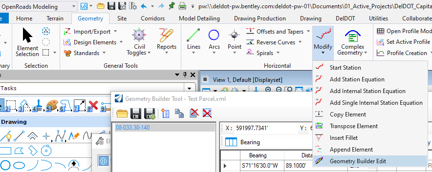
3.3.2 Select the Parcel and Left-Click to accept.
3.3.3 Follow steps 2.2.1 to 2.2.5 and save the file using the following format:
[PAN]_ADJUSTED.XML
(PAN = Parcel Assessment Number)
3.3.4 Repeat steps 3.3.1 to 3.3.3 for all parcels for the project.