Plan Annotation in ORD - GG2201
From DelDOT CADD Wiki
Introduction
The following workflow shall be used to annotate Grades using OpenRoads Designer (ORD) and the Civil Labeler. This process can be adapted for use in other software and environments at the users discretion.
Through this workflow, the user will annotate grades along features, such as edges of pavement and ditches, using the Civil Labeler tool in ORD. As part of this workflow, the following recommendations, background information and definitions are provided for clarity:
In general, it is recommended that all plan sheet annotation be performed within Drawing Models. No annotation should be performed with Sheet Models.
In certain instances it may be beneficial to perform annotation within the Design Model, such as with
Alignments
!
Alignment: Any Horizontal or Vertical Civil Ruled linear element.
that span multiple Named Boundaries or
Baselines
!
Baseline: Stationed Alignment used for Construction.
. This may be utilized at the users discretion.
In order to adhere to the DelDOT CADD Standards for Text Rotation, it may be necessary to generate Annotation Sections
!
Annotation Section: A segment of an Alignment where text display can vary by Orientation or Interval.
that are civil ruled to the original feature to be annotated. Each Annotation Section will correspond to a separate Civil Labeler style. For example, a long curb run could have four separate Annotation Sections:
- A long tangent section labeled at 50' intervals.
- One section of a curve to be labeled at 10' intervals with text oriented left.
- Another section of the curve to be labeled at 10' intervals with the text oriented right.
- The remainder of the curb to be labeled at 50' intervals.

Note: In the above example, the colors have been altered for illustrative purposes.
Note: In the above example, the green Annotation Section goes from left to right beginning at the Point of Curvature (PC) and ends at the nearest 10' interval before the change in text direction.
Please see Displaying Information on Grades and Geometrics for additional annotation information.
Grades and Geometrics Plan Annotation
This workflow requires the following:
- Each Feature to be annotated is positionally correct horizontally.
- Each Feature to be annotated is civil ruled. This allows for automatic updates as adjustments are made.
- Each Feature to be annotated has an active and continuous vertical alignment.
1. Create Civil Ruled features for Annotation
Note: When creating the DGN for the following steps, it is recommended that you use the GG Sheet Type and the DelDOT_Seed2D_th seed.
1.1 Open the Feature Definition Toolbar located under the OpenRoads Modeling Workflow > Geometry Tab > General Tools Group > Standards Drop Down.
Note: This toolbar is utilized extensively and it is recommend that it be permanentally docked within ORD.
1.2 Select Geometry_Labeling Feature Definition located under Linear > Grades. ! Additional Feature Definitions have been provided as an organizational aid to the Designer.
Note: Make sure you have the Use Active Feature Definition and Create 3D Automatically buttons toggled. They will have a blue background when toggled.

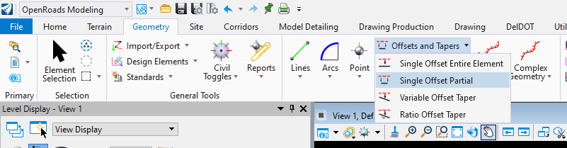
1.3 Click the Single Offset Partial tool located under the OpenRoads Modeling Workflow > Geometry Tab > Horizontal Group > Offsets and Tapers Drop Down.
1.4 Select the Alignment to be annotated and set Offset to zero.
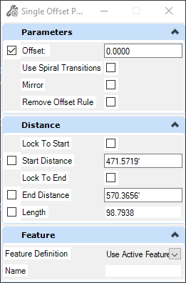
Note: By setting the Offset to zero and having Create 3D Automatically toggled, ORD will create Civil Ruled Features that will change dynamically when the underlying Corridor changes.
1.5 Enter or choose the Start Distance and End Distance and Data to accept.
Note: The Start Distance and End Distance should corrispond to the Annotation Sections mentioned at the beginning of this section.
1.6 Repeat steps 1.3 to 1.5 as necessary.
2. Annotate Alignments
It is recommend that the following be done within the appropraite Drawing Model of your Reference Composition file. Please refer to the Plan Production Guidelines - PL2101 for more information.
Note: By annotating in a Drawing Model, if your Alignment exceeds the bounds of the Named Boundary the Annotations may exceed the clipped area referenced into the Drawing Model requiring manual cleanup.
2.1 Select Civil Labeler under the OpenRoads Modeling Workflow > Drawing Production Tab > Labels Group. ! It is recommended that you close the Civil Labeler when switching between Models.

2.2 Select the appropriate Style located under Civil Labels > Plan - Linear > Grades and Geometrics.
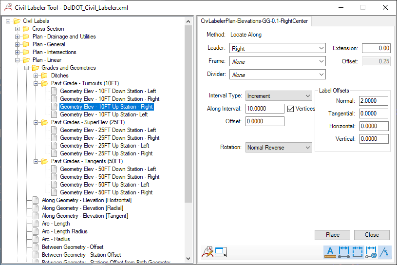
2.3 Pavt Grade - Turnouts (10FT):
2.3.1 Select the appropraite Label Style and hit Place.
2.3.2 Select the Civil Ruled Feature to be labeled and Left-click to accept.
2.4 Pavt Grade - SuperElev (25FT) and Pavt Grade - Tangents (50FT):
2.4.1 Select the appropraite Label Style and hit Place.
2.4.2 Select the Civil Ruled Feature to be labeled.
2.4.3 Select the Baseline that will dictate the stationing Left-click to accept.
2.5 Repeat the above as necessary.