Difference between revisions of "Proposed ROW Acquisition Creation - RW2202"
From DelDOT CADD Wiki
| Line 270: | Line 270: | ||
[[File:RW_002_06_02.png|link=|none]] | [[File:RW_002_06_02.png|link=|none]] | ||
<b>Note:</b> Page Sizes are tied to your Default Printer in your OS. If you do not see the appropriate Page Size you will need to set the correct printer. Internally the Department has set BluebeamPDF as the default, for this reason. Externally you may need to reach out to your internal IT staff. | |||
4.1.4 Click <b><i>File</b></i> > <b><i>Print</b></i> and select <b><i>Bluebeam PDF</b></i>. | 4.1.4 Click <b><i>File</b></i> > <b><i>Print</b></i> and select <b><i>Bluebeam PDF</b></i>. | ||
Revision as of 12:02, 13 July 2023
Introduction
The following workflow shall be used for the creation of Proposed Right-of-Way (ROW) Acquisitions for DelDOT projects. This workflow utilizes PW, MSCE, and ORD and is only valid for these applications. Older projects not utilizing these applications, such as those still using InRoads v8i, should utilize the previously established workflows for those applications.
Through this workflow the user will:
- Create and annotate all proposed acquisitions
- Export and combine the various forms of output data
- Generate the Data Sheets
Creation of Proposed Acquisitions
1. Create Proposed Acquisitions
Note: When creating the DGN for the following steps, it is recommended that you use the RW Sheet Type and the DelDOT_Seed2D_th_Bearings seed.
1.1 Draw Layout linework
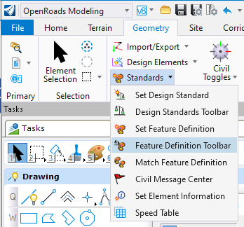
1.1.1 Open the Feature Definition Toolbar located under the OpenRoads Modeling Workflow > Geometry Tab > General Tools Group > Standards Drop Down.
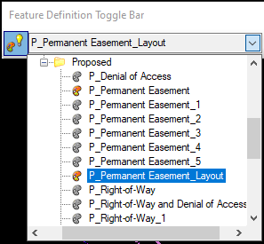
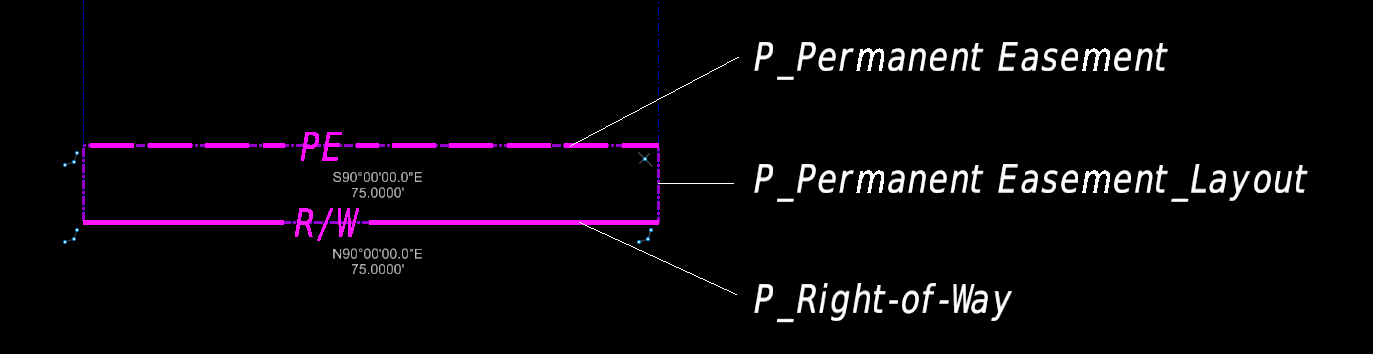
1.1.2 Set the appropriate layout Feature definition based on the type of acquisition to be created. These Feature Definitions are located under the Linear > Right-of-Way > Proposed folder. Layout Feature Definitions include:
- P_Permanent Easement_Layout
- P_Right-of-Way_Layout
- P_Temp. Construction Easement_Layout
Note: Make sure you have the Use Active Feature Definition button toggled. It will have a blue background when toggled.
1.1.3 Using the Horizontal tools, draw all segments of the Proposed Acquisition. These are located under the OpenRoads Modeling Workflow > Geometry Tab > Horizontal Group.
Note: These should be placed as individual elements as they will be joined later on.
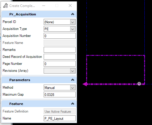
1.1.4 Select the Complex By Element tool located under the OpenRoads Modeling Workflow > Geometry Tab > Horizontal Group > Complex Geometry Drop Down.

1.1.5 Individual parcel elements should be joined using the Complex by Element tool in a clockwise direction starting with the element nearest to the frontage of the roadway and/or existing ROW.
Note: When hovering your mouse over the linework, an arrow will appear denoting the direction the line will be joined. Please note that it is possible to join clockwise lines and counterclockwise lines within the same parcel, so care must be taken. It is recommended that the tool Method be set Manual to verify the correct direction of each segment being joined.
1.1.6 Select the Proposed Acquisition and set the Feature Name in the Element Properties.
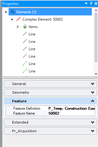
It is recommended that the Feature Names adhere to the following format:
- Each is a unique integer.
- R/W start at 40,000 and go up sequentially.
- TCE start at 50,000 and go up sequentially.
- PE start at 60,000 and go up sequentially.
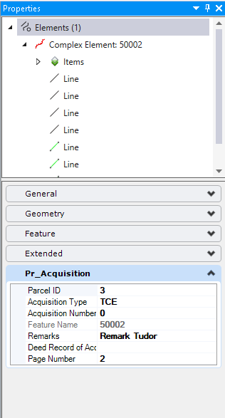
1.1.7 Select the appropriate Parcel ID for the proposed acquisition from the list and fill out the remaining data Fields under Pr_Acquisition . ! You can select multiple parcels and enter in common data between them all at once.
Note: Acquisition Number defaults to zero and should not be changed unless there are multiple Acquisitions.
Note: Remarks cannot contain Double-Quotations, Commas or Semi-Colons.
1.2 Draw Plan Production Linework
1.2.1 Once all of the Proposed Acquisition _layout lines have been drawn, draw the appropriate Plan Production (Display) lines with Horizontal Geometry using the appropriate Feature Definition. This step is required, as the layout lines are not included in the rendition settings.
Note: Alternatively, Element Templates and standard MicroStation elements can be used, but the above method causes ORD to automatically assign Civil Rules making the Plan Display linework dynamic.
1.3 Place and Label Points at All Vertices
1.3.1 Select the Point tool located under the OpenRoads Modeling Workflow > Geometry Tab > Horizontal Group > Point Drop Down.
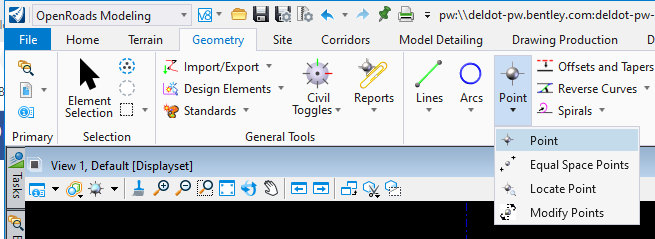
1.3.2 Click the dropdown next to Feature Definition and select Point > Proposed > P_Right of Way Point .
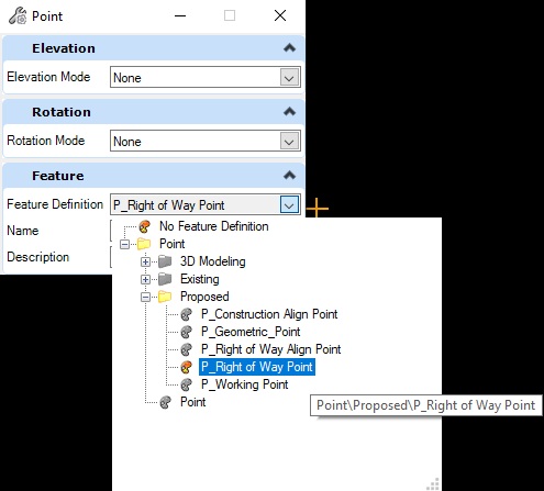
1.3.3 The Name field will function as the Point Number. The Name field defaults to 60,000 but will automatically go to the next available point number when placed and will automatically increment as you place points. It is recommended that all Point Numbers stay in the 60,000 point space regardless of the Acquisition Type (ie ROW, PE, TCE).
1.3.4 Precisely place points at all vertices (PC, PCC, PI, PT, etc...). It is recommended that points be placed in a clockwise direction around each parcel sequentially, starting from a previously established point. ! It is extremely important that all points be placed exactly over each vertex. This should be accomplished by tentative snapping. Bentley has videos on this topic available on their LEARN Server.

Do not place duplicate points at vertices that are shared by multiple parcels.
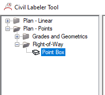
1.3.5 Open the Civil Labeler located under the OpenRoads Modeling Workflow > Drawing Production Tab > Labels Group.

1.3.6 Select Point Box located under Plan - Points > Right-of-Way .
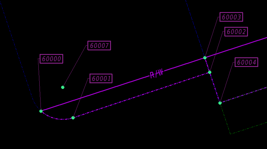
1.3.7 In ORD, select all points to be labeled. ! If selecting multiple points at once, be careful to only select Points. It is recommended that you isolate the RW_P_Point Location level.
1.3.8 In the Civil Labeler , click Place .
1.3.9 In ORD , left click to accept and place labels.
1.3.10 Move or Rotate each point label as necessary with the Move and Rotate command as necessary.
Note: When moving or rotating the Point Label the Leader will automatically adjust.
2. Export Data
2.1 Export Points
2.1.1 Select all points.
2.1.2 Run the Horizontal Point Report located under the OpenRoads Modeling Workflow > Geometry Tab > General Tools Group > Reports Drop Down.
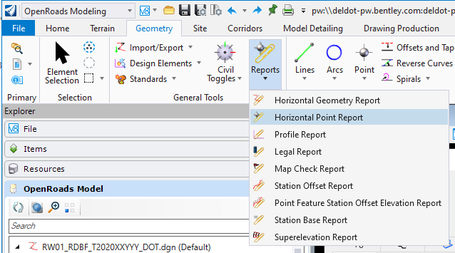
2.1.3 Left click to accept.
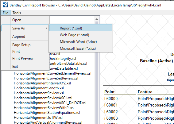
2.1.4 In the Bentley Civil Report Browser , go to File > Save As > Report (*.xml) .
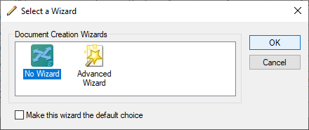
2.1.5 Choose No Wizard and hit OK .
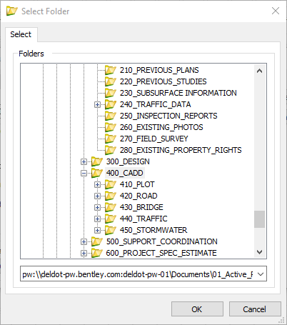
2.1.6 Select your 400_CADD folder and hit OK .
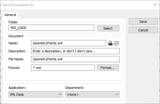
2.1.7 In the Name field enter GeometryPoints.xml and hit Save.
2.1.8 Click Check In .
2.2 Export Item Type Data
2.2.1 Open the DGN containing your Existing Parcels.
Note: The Item Type Reports look in the active file for any element matching the Report criteria, requiring you to be in the file that houses the data.
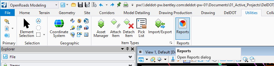
2.2.2 Click Reports located under the OpenRoads Modeling Workflow > Utilities Tab > Reports Group.
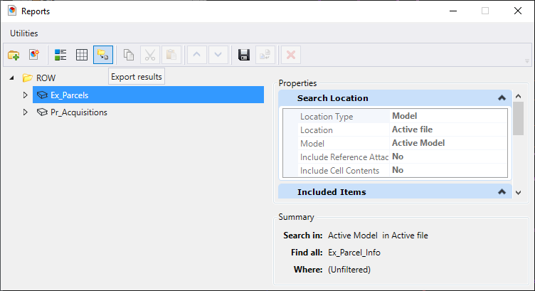
2.2.3 Select the ROW > Ex_Parcels report in the left panel and click the Export results icon from the toolbar.
2.2.4 Due to a bug with the current release or ORD , you will need to save the file locally and then upload to PW. (This Wiki will be updated when it is fixed.)
Note: It is recommended that you do not change the file name as later steps will automatically find these files based on their name.
2.2.5 Repeat the above steps for the Proposed Acquisitions and the Pr_Acquisitions report, making sure you are within the appropriate design file containing the proposed acquisition information.
2.3 Create Legal Report
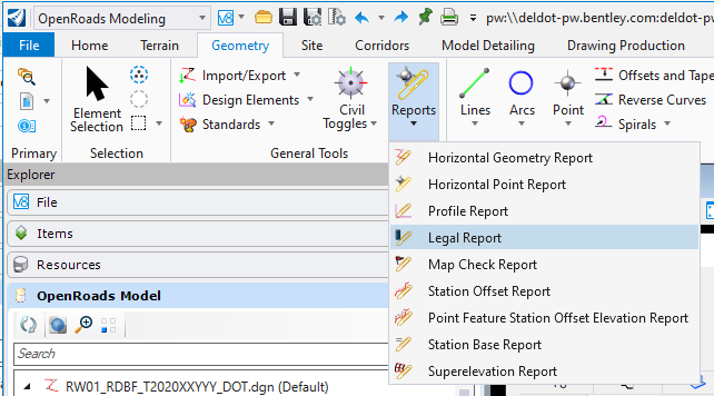
2.3.1 Run the Legal Report located under the OpenRoads Modeling Workflow > Geometry Tab > General Tools Group > Reports Drop Down, and follow the Tool Prompts.
Note: It is recommended that you create one Legal Report for all Acquisitions.
Note: It is recommended that you set your level display so that only the layout levels (*_Layout) and your Alignments are displayed.
2.3.2 Locate First Element : This will be each Acquisition. Select each taking, per parcel, in the order noted below. Once finished, right-click to continue.
Note: You must select each Acquisition manually in the following order per parcel: RW/PE, RW, PE, TCE.
Example:
2.3.2.1 Parcel 1: RW, TCE-1, TCE-2
2.3.2.1 Parcel 2: PE, TCE
2.3.2.1 Parcel 3: RW/PE, RW-1, RW-2, PE-1, PE-2, TCE.
2.3.3 Locate Parent : Right-click to skip selecting a Parent.
2.3.4 Locate Primary Reference : This is your Primary Alignment. Select your Alignment.
2.3.5 Primary Reference Alignment:Bandwidth : This is the Offset threshold that a point will reference your Primary Alignment. Any point past this distance, will reference the nearest Secondary Alignment, if selected in the next step.
2.3.6 Locate First Secondary Reference Element : This, if selected, will handle points outside of the Primary Alignment's Bandwidth. When using multiple Secondary Alignments, the one with the lowest offset will be used first. Right click to skip or when finished selecting Secondary Alignments.
2.3.7 In the Bentley Civil Report Browser , go to File > Save As > Report (*.xml) .
2.3.8 Choose No Wizard and hit OK .
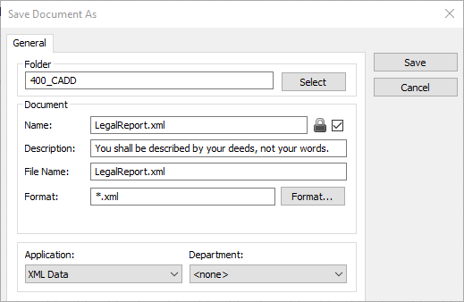
2.3.9 Select your 400_CADD folder and hit OK .
2.3.10 In the Name field enter LegalReport.xml and hit Save.
2.3.11 Click Check In .
2.3.12 Leave the Bentley Civil Report Browser open.
3. Combine Output Data
3.1 Under the OpenRoads Modeling Workflow > DelDOT Tab > Plan Type Group set your Plan Type to RW- Right-of-Way Strip File.
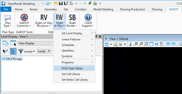
3.2 Select the ROW Data Tables located under the DelDOT Plans Group > Right of Way Drop down.
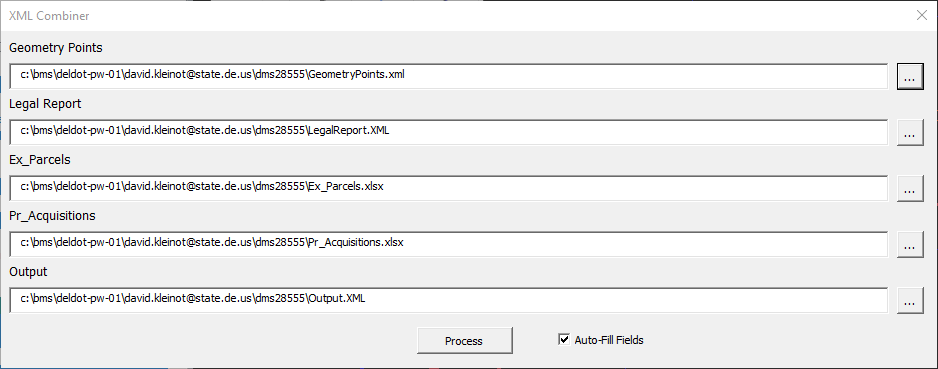
3.3 Click the Ellipsis button next to the Geometry Points field to browse for your Geometry Points file, which should be located in the 400_CADD folder.
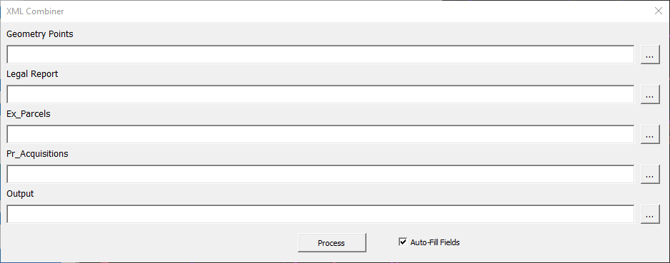
Note: If Auto-Fill Fields is checked, the program will attempt to find the other files after one is entered. 3.4 Repeat for the legal Report, Ex_Parcels, Pr_Acquisitions and Output Fields.
Note: If a specific Output file already exists with the name provided in this field, the program will overwrite its contents. It is recommended that the Output file be named Output.xml.
3.5 Click Process .
4. Generate Deliverables
4.1 Generate Data Tables
4.1.1 In the Bentley Civil Report Browser , go to File > Open and load Output.xml generated in Step 3.4 through 3.5.
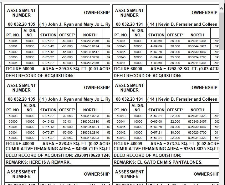
4.1.2 Under LegalDescription select DelDOT_ROW_DataTables.xsl .
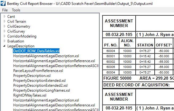
Please note: The output should appear in two columns as shown below. If this is not the case, please contact DOT_CADDSupport@delaware.gov and see section 4.4:
4.1.3 Under File > Page Setup set the following options and click OK:
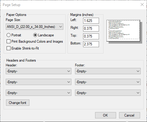
Note: Page Sizes are tied to your Default Printer in your OS. If you do not see the appropriate Page Size you will need to set the correct printer. Internally the Department has set BluebeamPDF as the default, for this reason. Externally you may need to reach out to your internal IT staff.
4.1.4 Click File > Print and select Bluebeam PDF.
Note: This was also tested with the Adobe PDF printer and should work with any PDF printer provided you have the correct PDF Paper size.
4.1.5 Click Preferences and set Orientation to Landscape.
4.1.6 Click Advanced... and set Paper Size: to ANSI_D_(22.00_x_34.00_Inches).
4.1.7 Click OK until you're back to the Print Dialog and then click Print.
4.1.8 In the Save As dialog, select a location, change the File name and click Save.
If the PDF does not open automatically, open the PDF.
4.2 Sheet Data Tables using Bluebeam
This is the preferred way to sheet the Data Tables. If you are unable to use Bluebeam, see section 4.3.
The following assumes you are familiar with the Bluebeam Resource Guidelines - BB2101.
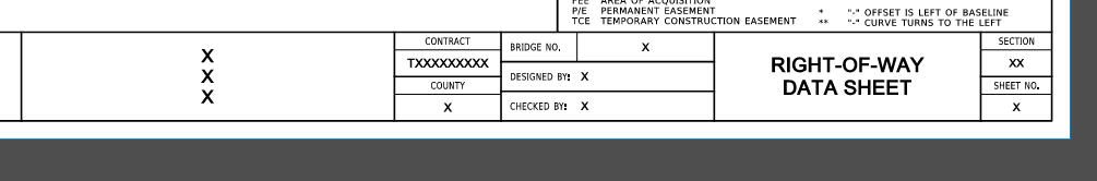
4.2.1 Under the Right-of-Way section select ROW Sheet Border and place on sheet.
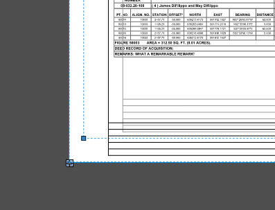
4.2.2 Move and snap the ROW Sheet Border to the bottom left corner of the Page.
4.2.3 Fill out all fields with X's by double clicking directly on top of the X.
4.2.4 Right click on the ROW Sheet Border and select Apply to Pages... .
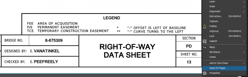
4.2.5 Select All Pages from the drop down and click OK .
4.2.6 Update the SHEET NO. on each sheet as necessary.
4.2.7 Go to Document > Flatten....
4.2.8 Under Options confirm that Group , at a minimum, is selected and click Flatten. It is recommended that Allow Markup Recovery (Unflatten) is unchecked.
Note that leaving this unchecked will not allow you to unflatten and change the Sheet Border so it is recommended that this be done as the final step before sending out the planset.
Note: If you have added any other items to the PDF (i.e. Revision Blocks or other markups) check the appropriate item under Options. ! You can check Type directly under Options to select all.
4.3 Sheet Data Tables using MicroStation
This method is provided for those who do not have access to a Standard License of Bluebeam.
4.3.1 Prepare the Sheet Models in MSCE per the current guidance in Plan Production Guidelines - PL2101.
4.3.2 Under the Raster Manager, Attach the Output PDF from 4.1.9.
4.4 Creating the PDF using Microsoft Edge
This section should only be followed if step 4.1.2 did not function properly.
A problem was found with ORD where the Civil Report Browser was not displaying the information correctly and has been fixed internally. Please have your CADD / IT section contact DOT_CADDSupport@delaware.gov and we will provide the Registry Fix that addresses the issue.
As an alternative, the following instructions has been confirmed to work without the above fix.
4.4.1 In the Bentley Civil Report Browser, go to File > Open and load Output.xml generated in Step 3.4 through 3.5.
4.4.2 Under LegalDescription select DelDOT_ROW_DataTables.xsl.
4.4.3 Under File > Save As choose Web Page (*.html).
4.4.4 Open the file in a Web Browser. The following instructions are for using Microsoft Edge but Internet Explorer and Google Chrome have also been tested.
Please note that there will be a lot of overlap.
4.4.5 Go to Settings and choose Print....
4.4.6 Set your Printer to Bluebeam PDF.
Note: This was also tested with the Adobe PDF printer and should work with any PDF printer provided you have the correct PDF Paper size.
4.4.7 Set your Layout to Landscape.
4.4.8 Under More Settings set Paper Size to ANSI_D_(22.00_x_34.00_Inches), Scale (%) to Actual Size and Quality to 600 dpi.
4.4.9 Set Margins to Custom and set the following options:
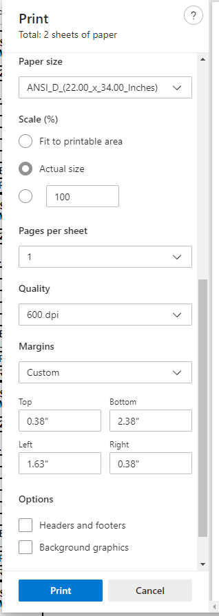
Note: Make sure to uncheck Headers and footers and Background graphics.
4.4.10 Click Print and save the PDF.
4.4.11 Continue with section 4.2 or 4.3.
4.5 Additional Deliverables
As part of a Right-of-Way plan submission, the Data sheets in Excel file format and the Property Description in Word format should be made available via PW.
4.5.1 It is recommended that this be done in conjunction with Section 4.1.
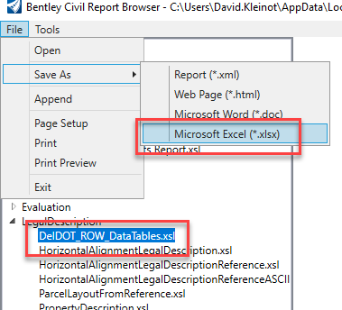
4.5.2 Inside of the Bentley Civil Report Browser select Legal Description > DelDOT_ROW_Tables.xsl.
4.5.3 Go to File > Save As > Microsoft Excel (*.xlsx) and save the file to the 280_EXISTING_PROPERTY_RIGHTS folder.
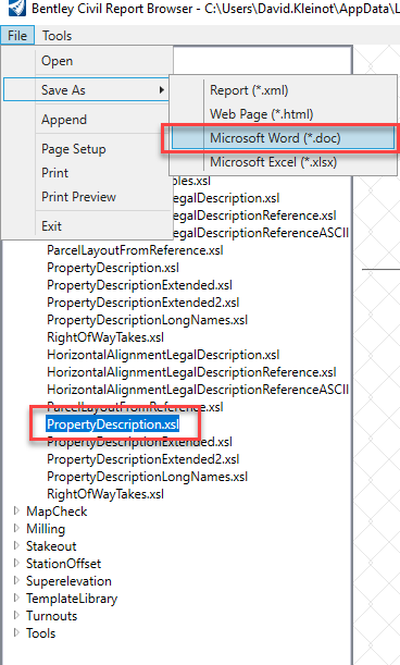
4.5.4 Select Legal Description > PropertyDescription.xsl.
4.5.3 Go to File > Save As > Microsoft Word (*.doc) and save the file to the 280_EXISTING_PROPERTY_RIGHTS folder.