Template
From DelDOT CADD Wiki
Introduction
This is a Template to use for all Wiki pages moving forward. As changes are made, this template will be updated. Wiki formatting for Bold, Bold + Italic and Italic will be used.
The following is a ToolTip. It is not required to be used. It is intended as an aid to the reader and is not necessary for the user to complete the process.
!
The Introduction will conver a breif overview of the process.
Revision Summary
This section provides a summary of significant revisions and additions to WikiPage. To view the full history, select View History in the top right corner of the MediaWiki page. This document is intended to be an ongoing process that is frequently updated. This section will track revisions and additions to this document. ! Not entirely sure how I feel about this one yet. The View History that is baked into MediaWiki is too specific I think. The intent of this is to provide updates when we make large changes, like a new section...
- 1/01/2021: Initial Release
- 1/02/2021: Added section 4 "Don't be a dumb a$$"
- 1/03/2021: Added section 5 "Seriously?! Don't contact DTI for CADD support"
Name of the Process
1. First major step title
1.1 First sub step title.
Instructions for first sub step.
1.2 Second sub step title.
Instructions for second sub step. ! Note on Images:
1.2.1 Second Sub-Sub step title. Instructions for Second sub-sub step.
1.3 PW: Create the Reference Composition file.
The Reference Composition (RC) is a single DGN that combines all your Strip References into one file. This makes attaching and clipping references much easier. This also provides flexibility when working with Distributed Designs and ORDs built in Sheeting processes. ! See section 5.5 and 5.6 for more information on reference file structure.
1.3.1. Follow steps 1.2.1 through 1.2.5. Set SHEET TYPE to RC, DRAWING TYPE to BF and click Next.
There are three types of drawings:
BF – Base / Strip File.
This will be all common reference files (ie PC, FS, RW).
CM – Civil Model File: This will be any modeling files (ie MD) generated in Civil Design Software (ie ORD).
SF – Sheet File:
This will be all Sheet Models. Generally speaking, these DGNs will contain a single Sheet Model and can be thought of as a replacement to .PRF or .i files.
1.3.2. Click Next through the subsequent prompts leaving all values at their defaults and click Finish at the end to create the file.
1.4. PW: Create the Sheet Border file.
The following section will create the Sheet Border file and populate it. Refer to section 1.2 for detailed instructions on creating files in ProjectWise.
1.4.1. Follow steps 1.2.1 and 1.2.2.
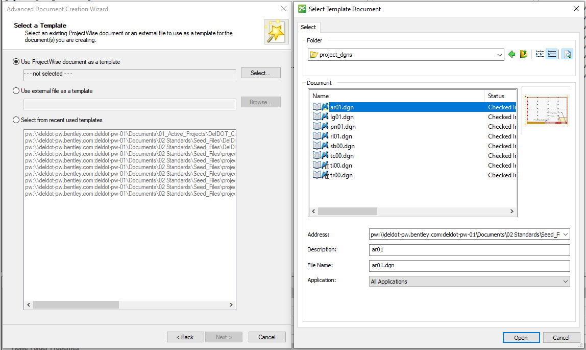
1.4.2. Select Use ProjectWise Document as a template and click the Select… button. Navigate to the 02 Standards > Seed_Files > project_dgns, select sb00.dgn from the list, hit Open and then hit Next.
1.4.3. Set your SHEET TYPE to SB, your DRAWING TYPE to BF and click Generate.
1.4.4. Follow the rest of section 1.2 changing options as necessary. It is recommended that you leave the file associated with MSCE.
1.4.5. Open the Sheet Border file.
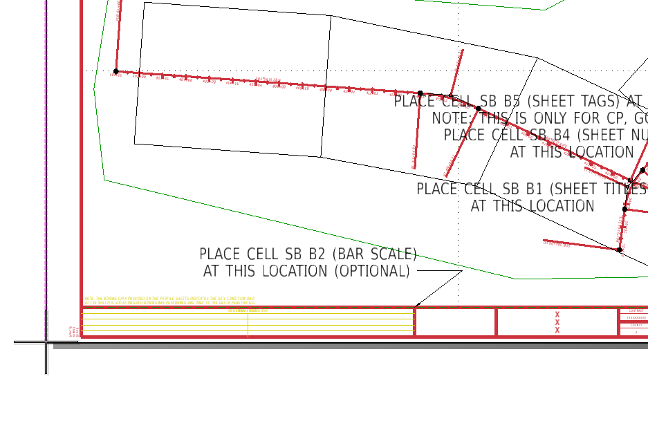
1.4.6. Place cells as necessary (ie SB_B2, SB_B1, SB_B4, etc…).
1.4.7. Fill out information as necessary (ie Title, Contract, County, etc…), close and check in file.
1.5. MSCE: Open the Reference Composite file and reference in Strip Reference files.
! ORD may be used in place of MSCE, but MSCE cannot be used in place of ORD. As a rule of thumb, it is recommended to open a file in MSCE when ORD is not required. In this section, you will setup the RC file you created in section 1.3.
1.5.1. Double clicking a file in PW will open it in its assigned program. To open with a specific program, right-click on the file and choose Open With…
1.5.1.1. Choose the program you want to open with. If you do not see the program you want in the list, click Browse to pick from the list of approved programs.
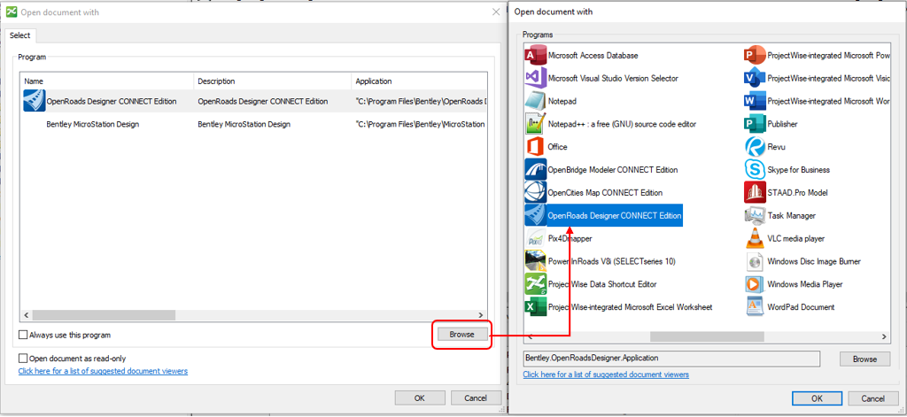
1.5.1.2. If necessary, check Always use this program and Open document as read-only and hit OK.
!
Please note what checking the following options is doing:
Always use this program will associate the file extension with a program. So, if you check this for a DGN, it will always open DGNs with that program.
Open document read-only will open the document read-only. Doing this in MSCE/ORD is not recommended as you will not be able to do much of anything in the file. It is recommended instead that you open the file regularly and then, if you don’t want to commit the changes, click Free when asked if you want to check the file back in.
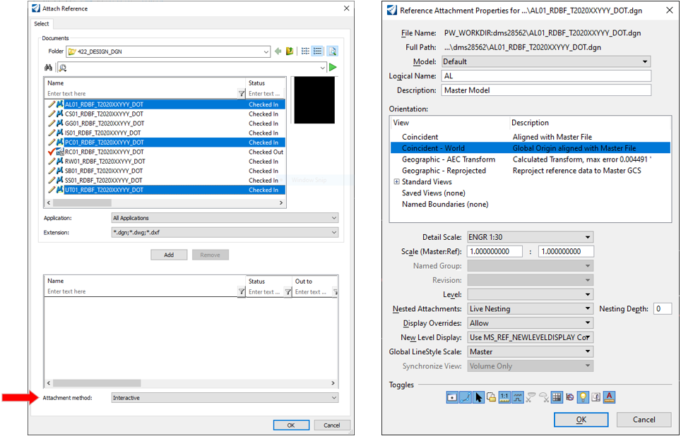
1.5.2. Once inside the file, open the Reference dialog, go to Tools > Attach… and select the appropriate files. It is recommended to set Attachment method to Interactive at the bottom of the window and hit OK. Setting this to Interactive will bring up the Reference Attachment Properties Dialog with more options (see step 1.5.3). Setting this to Coincident World will bypass the Dialog and should be used with caution.
1.5.3. Select Model and fill out Logical Name as necessary for each file you are attaching and press OK. If you selected multiple files in 1.5.2, you will see this dialog box multiple times and will need to fill out the fields and click OK for each.
2. Primary Sheets (CP, GG, RW, SS, etc…)
Primary Sheets are the Cross Referenceable ! Cross Referenceable sheets are those that get the Sheet Identifier and are limited to Construction Plans (CP); Grades and Geometrics (GG); and Signing, Striping and Conduit Plans (SS) geolocated plans that follow the construction alignment. Examples of this include Construction Plans, Grades and Geometrics and Signing and Striping. The following process will create multiple Drawing Models in the RC DGN and separate the Sheet Models into individual DGNs.
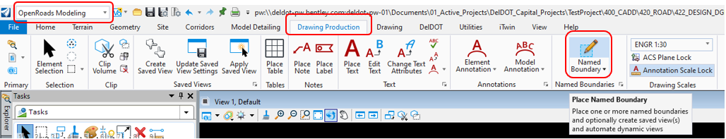
2.1. In ORD, open the Reference Composition file created in section 1.3, select Place Named Boundary from the Ribbon and select your alignment.
The following section will create a template for the Primary Sheets that will be copied for each set of plans (ie CP, GG, SS, etc).
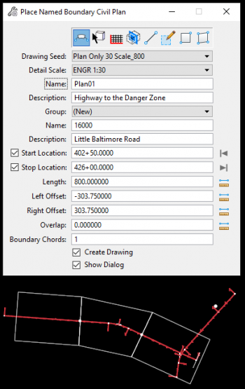
2.1.1. In the Place Named Boundary dialog, select the first option, Civil Plan.
2.1.2. Drawing Seed: Select the appropriate seed.
Example: Plan Only 30 Scale_800 is 30 scale and runs 800 feet along the alignment
2.1.3. Detail Scale: This is set by the Drawing Seed.
2.1.4. Name: Enter CP01 for the name. ! For primary sheets, this will be used as a template to create the other sheets. ORD will automatically increment for each boundary it creates.
2.1.5. Description: Optional. Enter a Description for Named Boundaries.
2.1.6. Group: If you need to add to a group, choose it from the list, otherwise leave as (New).
2.1.7. Name: Recommended to be the name of your Alignment.
2.1.8. Description: Recommended to be your Road Name.
2.1.9. Start Location: If you know your start station you may enter it in. ! This is the location on your alignment where you want sheets to start. You can enter it manually or graphically.
2.1.10. Stop Location: If you know your stop station you may enter it in. ! This is the location on your alignment where you want sheets to end. You can enter it manually or graphically.
2.1.11. Length: This is set by Drawing Seed. ! This is the Length of the Named Boundary and dictates how much will show up on a sheet. These values are set by the Drawing Seed and should not be changed. Pick a different Drawing Seed to change.
2.1.12. Left Offset: This is set by Drawing Seed.
2.1.13. Right Offset: This is set by Drawing Seed.
2.1.14. Overlap: This is set by Drawing Seed.
2.1.15. Boundary Chords: This is set by Drawing Seed.
2.1.16. Create Drawing: Confirm this is checked.
2.1.17. Show Dialog: Confirm this is checked.
2.1.18. If you did not enter the Start Station in 2.1.9, select this graphically.
2.1.19. If you did not enter the Stop Station in 2.1.10, select this graphically.
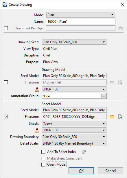
2.1.20. Data to Accept and the Create Drawing dialog will come up.
2.1.21. Leave all options at their default. It is recommended to have Add to Sheet Index and Open Model unchecked.
2.1.22. Sheet Model > Filename: Check the box and hit the Create New Sheet File button.
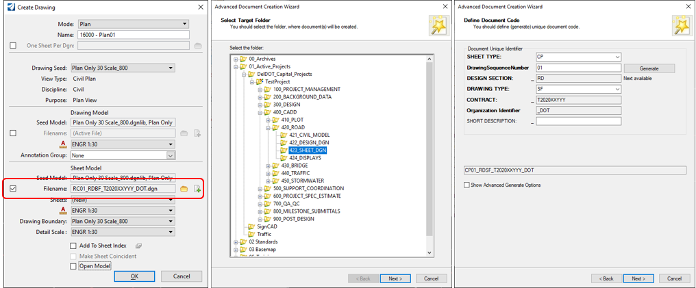
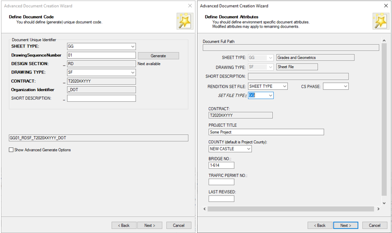
2.1.23. This will kick off a similar process to section 1.2 and 1.3. Select your SHEET_DGN folder, set SHEET TYPE to CP, set DRAWING TYPE to SF and click Generate.
Note: You will be using CP as a template to create the other Primary Sheets.
2.1.24. Click Next through the subsequent prompts until you get to Define Document Attributes.
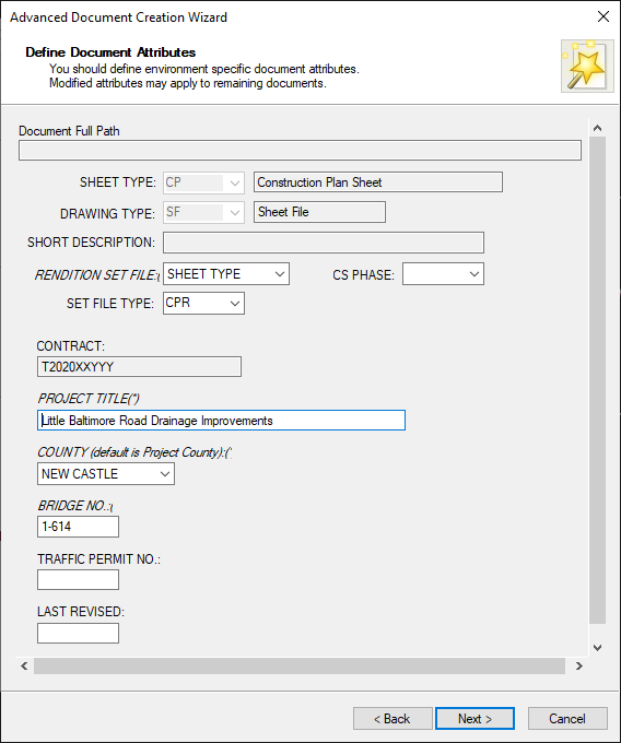
2.1.25. Set RENDITION SET FILE to SHEET TYPE and confirm that SET FILE TYPE is set correctly. Fill in the other fields as necessary. Click Next through the subsequent prompts and then click Finish to create the file.
2.1.26. It is recommended to keep Add to Sheet Index and Open Model unchecked. Click OK on the Create Drawing dialog to close it.
2.1.27. Repeat steps 2.1.1 through 2.1.21 for any additional alignments. On step 2.1.22 select the file you created previously instead of creating a new one for any additional alignments.
2.1.28. Once finished, shut down ORD and check in any files.
2.2. Run batch program to set Sheet Model locations.
The following section will move and rotate the Drawing Model, Sheet Boundary and Sheet Model to the appropraite location, ensuring the PDF plans will be geolocated. By default, these are set to 0,0.
2.2.1. In PW, open CP01 (created in step 2.1.22) with OpenRoads Designer.
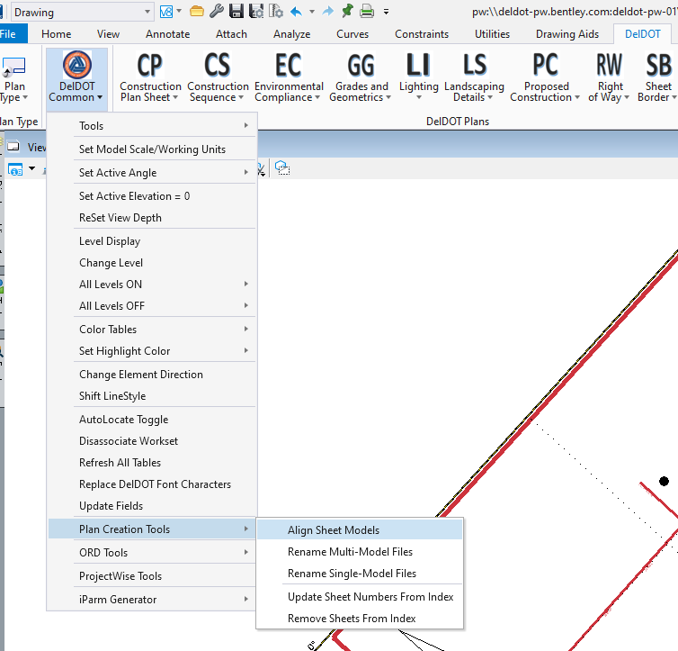
2.2.2. In the Ribbon, go to the DelDOT tab > DelDOT Common > Plan Creation Tools > Align Sheet Models
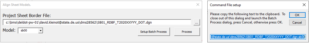
2.2.3. Click the ellipsis button (…) on the right side of the Project Sheet Border File.
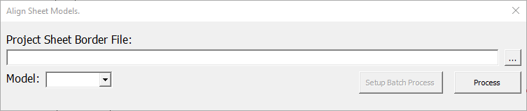
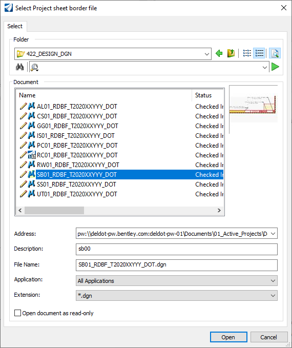
2.2.4. Select the Sheet Border file you created in section 1.4 and hit Open.
2.2.5. Select the Setup Batch Process button, Right-click and Copy the highlighted text from the Command File Setup dialog and press Cancel to dismiss both dialogs. ! Note: Use the Process button if you only want to process the current DGN.
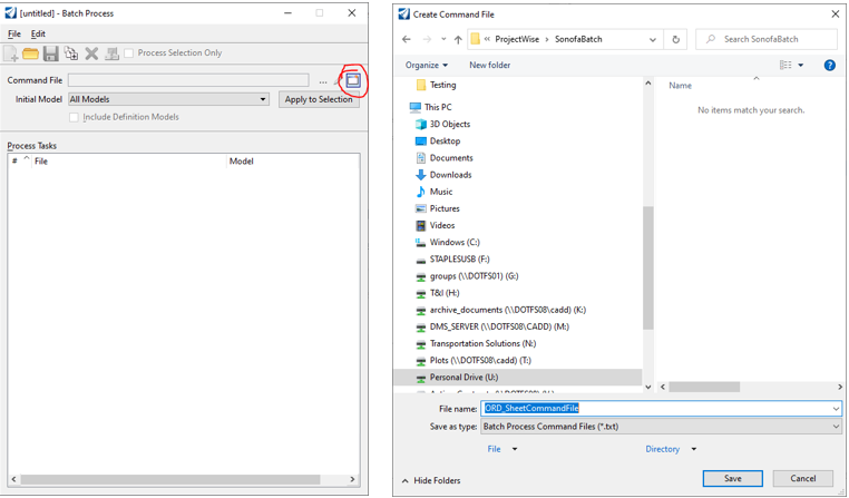
2.2.6. In the Batch Process dialog box, select Create a new command file and hit cancel on the Advanced Document Creation Wizard to save the file locally. Name it and hit Save.
2.2.7. Your file will load in your default Text file editor. Paste the text copied in step 2.2.5 onto line 10.
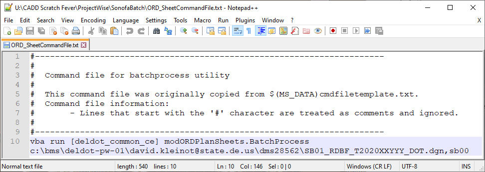
2.2.8. Save and close the text file.
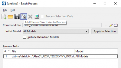
2.2.9. In the Batch Process window, it will have loaded your Command file.
2.2.10. Confirm that Initial Model is set to All Models.
2.2.11. Click the Add Files or Directories to Process and navigate to CP01 (created in 2.1.22).
2.2.12. All files will be listed in the Process Tasks section.
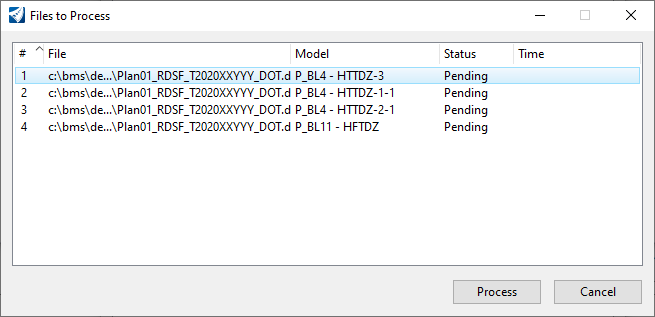
2.2.13. Click Process Batch Process Job to bring up the Files to Process dialog.
2.2.14. Confirm all files and models are loaded and click Process.
2.2.15. When it is done, click Done and close out of all Batch Process dialogs.
2.2.16. Add common cells to each sheet model as necessary (ie SB_B2x, SB_B1, SB_B4, etc…). ! If there is anything else you need to do to each sheet, now is the time as this will be the template for all other Primary sheets.
2.2.17. Close ORD and check in all files.
2.3. Copy and Paste CP01 to create Primary Sheets (ie CP, SS, GG, RW, etc).
The following section will duplicate the CP01 file (created in 2.1.22) inside of PW for each of the Primary Sheets.
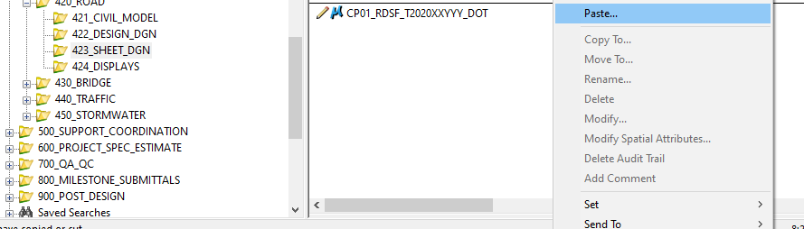
2.3.1. In PW, right-click on the CP01 file (created in 2.1.22) and click Copy.
2.3.2. Right-click in white-space, select Paste… and hit Yes on the popup.
2.3.3. This will bring up the Advanced Document Creation Wizard. Set the following options:
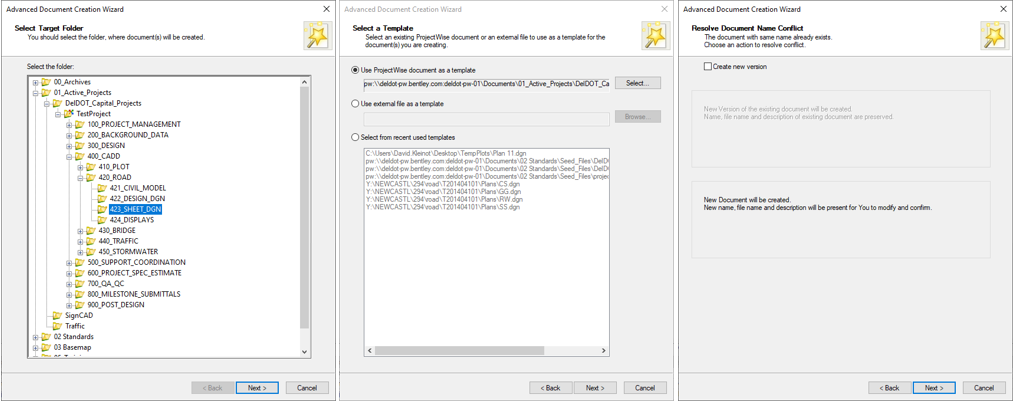
2.3.4. Set the SHEET TYPE to the appropriate, set DRAWING TYPE to SF and click Generate.
2.3.5. Click Next through the subsequent dialogs making sure to set the RENDITION SET FILE to SHEET TYPE and selecting the appropriate SET FILE TYPE.
2.3.6. Repeat steps 2.3.2 through 2.3.5 for each Primary Sheet.
2.4. Run batch program to rename models for each file created above.
The following section will rename the models for each DGN you specify. By default, they will be incremented off of the base name, in this case CP01. The model name is important, as it is what shows up in the Sheet Index and in the name of the PDF.
2.4.1. In PW, open one of the files created in step 2.3.2 with MSCE.
2.4.2. In the Ribbon, go to the DelDOT tab > DelDOT Common > Plan Creation Tools > Rename Multi-Model Files. ! Note, this will only rename the Models, not the View Groups. If you want to also rename the view groups, modify the command line to use the following text: “vba run [deldot_common_ce] modORDPlanSheets_v2. Batch_Multi_Sheet_PerDGN_Rename TRUE”
See steps 2.2.6 to 2.2.15 for more details[D22].
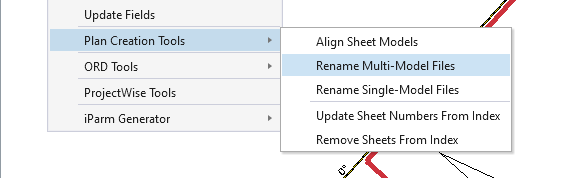
2.4.2.1. Rename Multi-Model Files: This is intended to be used when you have Multiple Models in a single DGN.
ie. CP01.dgn contains Sheet Models for CP01 – CP##
2.4.2.2. Rename Single-Model Files: This is intended to be used when you have one Model in a DGN.
ie. each CP##.dgn contains only one Sheet Model.
2.4.3. Make sure Initial Model is set to Default Model Only before importing files.
2.4.4. Click Add Files or Directories to Process and open all necessary files created in steps 2.3.2 through 2.3.5. Click Process Batch Process Job.
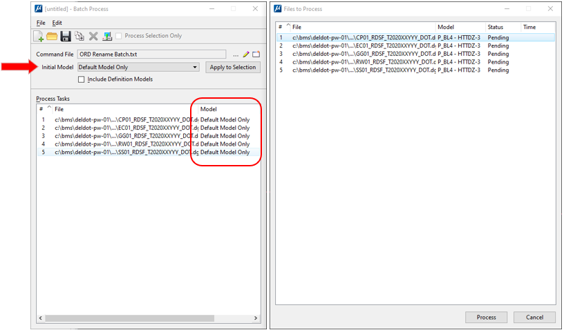
2.4.5. Confirm all desired file are loaded correctly and hit Process.
2.4.6. Once finished, you can close the file and check back into PW.
2.5. Add to Sheet Index.
The following section will build out the Sheet Index. The Sheet Index handles sheet numbering and order of sheets in the plan set.
2.5.1. Load one of your files from _SHEET_DGN in MSCE or ORD.
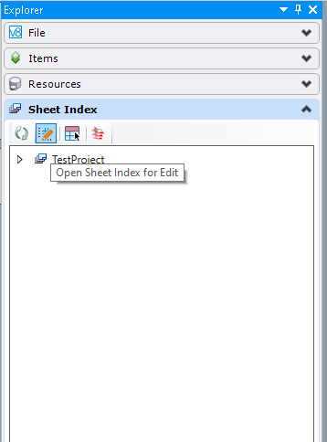
2.5.2. Make sure the Explorer is open and the Sheet Index tab is open.
To open, in the Ribbon go to Home > Explorer, or use the search-bar in the top right corner.
2.5.3. Click Open Sheet Index for Edit.
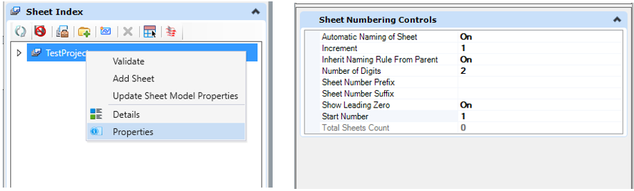
2.5.4. Select your Project and click Properties and set the following options. Crtl + i will load the Properties Panel ! This is the same place you view element information such as the length of a line, or the Start and End coordinates of a point. Alternatively, you can click the third Icon shown in the screenshot “Manage Sheet Index”. if it is not open.
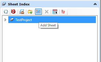
2.5.5. Click the Add Sheet button.
2.5.6. Select the sheet files created in step 2.3.2 and hit OK.
2.5.7. This will bring up the Add Sheet dialog. Select the sheet models you want to add to the Sheet Index and hit OK.
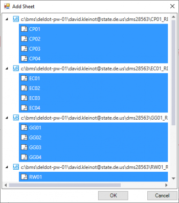
Important note: You cannot select everything and hit OK or ORD will only bring in the first models. You must select each sheet model individually and hit OK.
To get the selection shown on the left:
2.5.7.1. Click on CP01, hold the Shift key and select CP04.
2.5.7.2. Hold the Ctrl key and select EC01.
2.5.7.3. Hold the Shift key and the Ctrl key and select EC04.
2.5.7.4. Repeat 2.5.7.2 and 2.5.7.3 for all remaining Sheet Models.
!
Alternatively, you can select everything and then hold the Ctrl key and deselect each file leaving the Sheet Models selected.
2.5.8. Click Check In for all files.
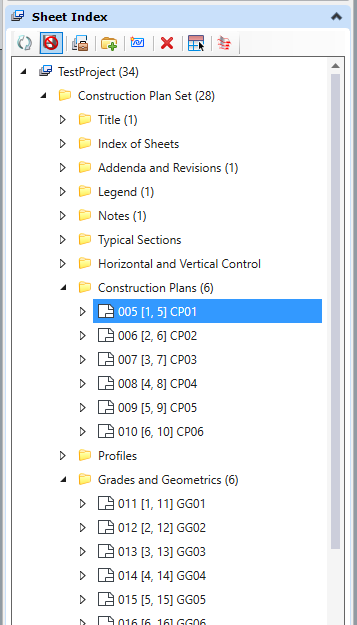
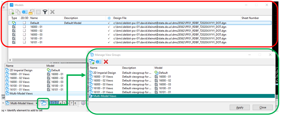
2.5.9. You should now see all the Sheet Models you added to the Sheet Index. You will need to drag the sheets to the individual folders as shown below. ! Alternatively, you can right click on a folder (ie Construction Plans) and select Add Sheet to add Sheet Models directly to that folder.
2.5.10. Click Make Sheet Index Read Only.
2.5.11. Close MSCE and check in any files.
3. Secondary Sheets (TC, TS, HV, IS, etc…)
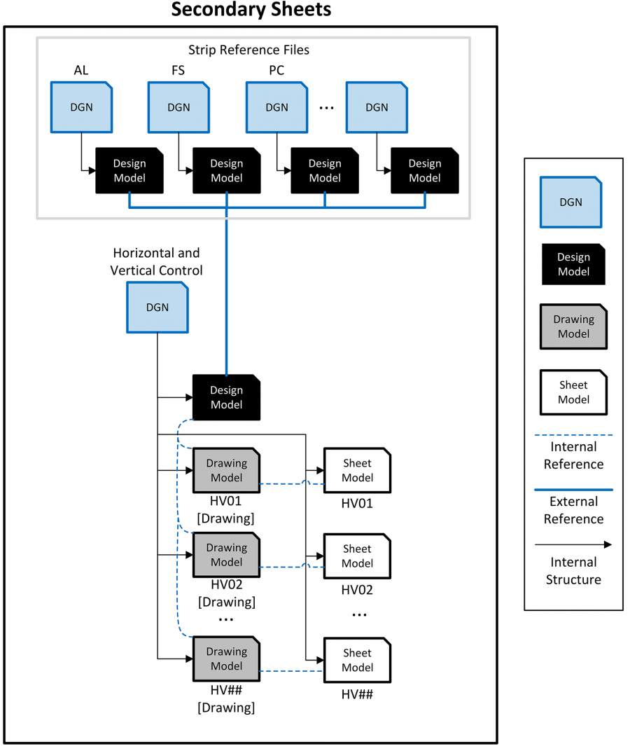
Secondary Sheets are non-cross referenceable sheets that may be geolocated and do not directly follow the construction alignment. Examples of this include the Title sheet, Detail sheets and Horizontal and Vertical sheets. The following process will create DGNs with Drawing Models and Sheet Models.
3.1. Create generic Secondary Sheets (AR, LG, PN, etc…).
3.1.1. In PW, right-click and choose New > Document… ! See section 1.2 for more details on this process.
3.1.2. Select the appropriate seed to use as a template for the sheet being created by navigating to 02 Standards > Seed_Files > project_dgns.
3.1.3. Fill out all appropriate info and repeat this process for all files as necessary.
3.2. Create georeferenced Secondary Sheets (HV, IS, etc…).
3.2.1. In PW, right-click and choose New > Document… ! See section 1.2 for more details on this process.
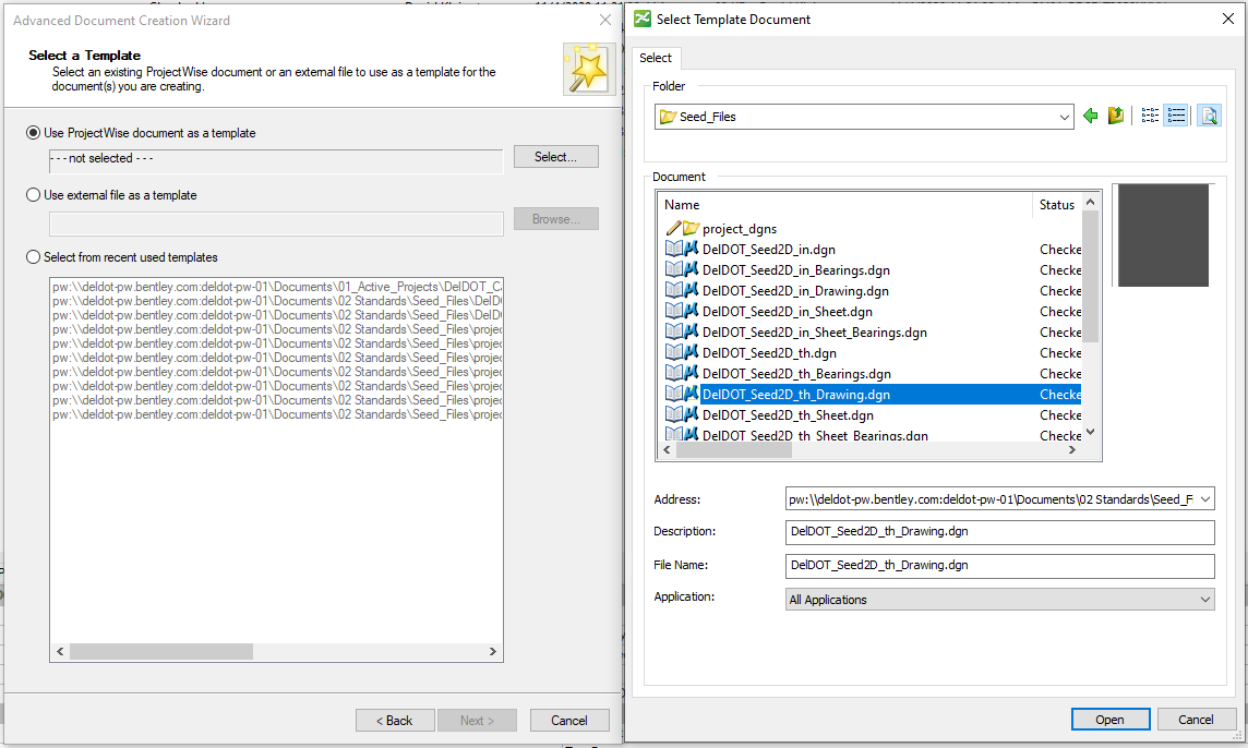
3.2.2. Select the appropriate Drawing seed to use as a template by navigating to 02 Standards > Seed_Files.
3.2.3. Fill out all appropriate info to create the DGN.
3.2.4. In MSCE, open the file.
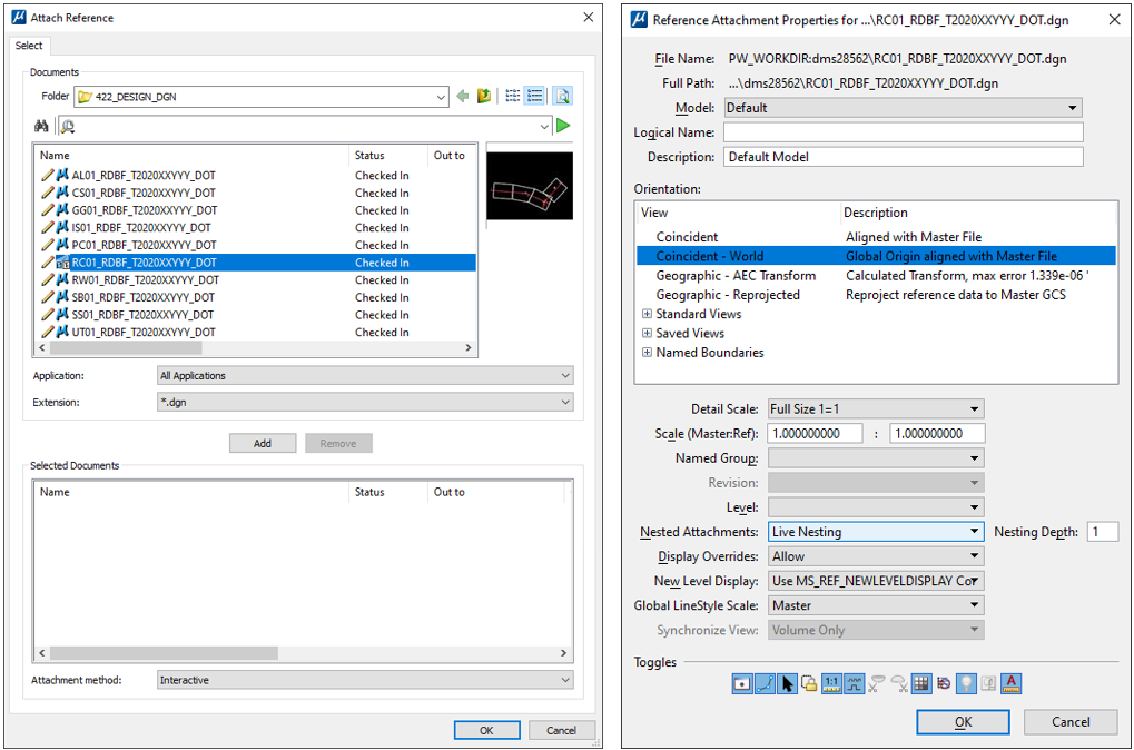
3.2.5. Open the References dialog, go to Tools > Attach… and select your RC file.
3.2.6. Make sure Attachment Method is set to Interactive and hit OK.
3.2.7. Make sure Orientation is set to Coincident – World and Nested Attachments is set to Live Nesting with a Nesting Depth of 1 and hit OK.
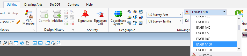
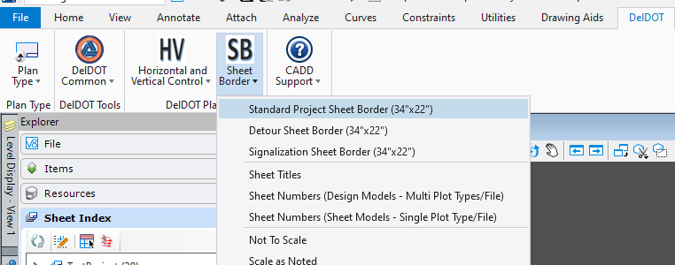
3.2.8. Set your Drawing Scale.
3.2.9. In the DelDOT menu, set your Plan Type. Select Sheet Border > Standard Project Sheet Border (34” x 22”) and temporairly place a Sheet Border. Move and rotate as necessary.
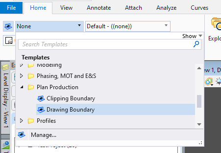
3.2.10. In the Home tab, set your active Element Template to Plan Production > Drawing Boundary.
!
It is recommended that you have Element Template Association turned on.
This is located immediately to the left of the Element Template selection field. When on, it will have a blue background.
This will cause the elements to automatically update if the CADD standards are changed.
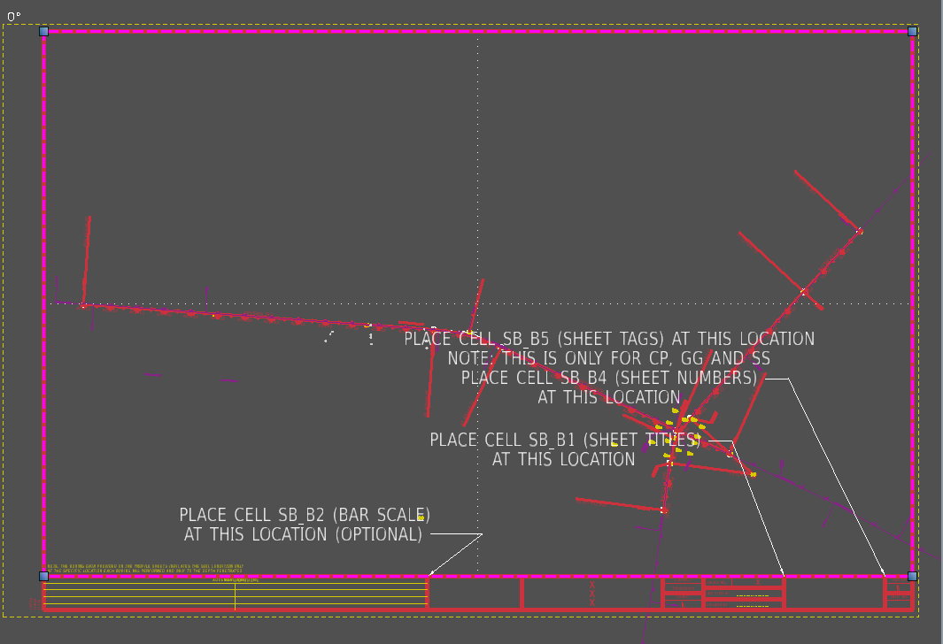
3.2.11. Create a closed shape around the inner area of the temporary Sheet Border. ! This will be your “Safe area” for placing Schedules and Cells.
3.2.12. In the Home tab, set your active Element Template to Plan Production > Clipping Boundary.
3.2.13. Place a closed shape around the area to be contained by the Sheet Border.
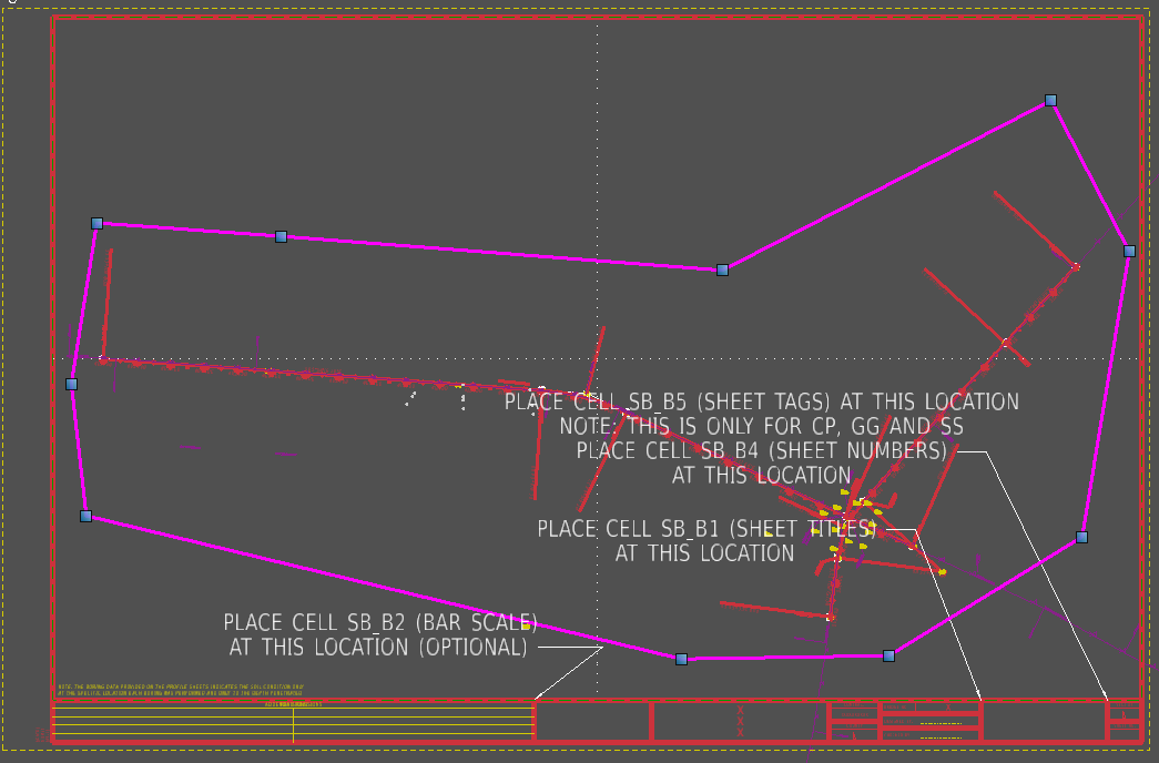
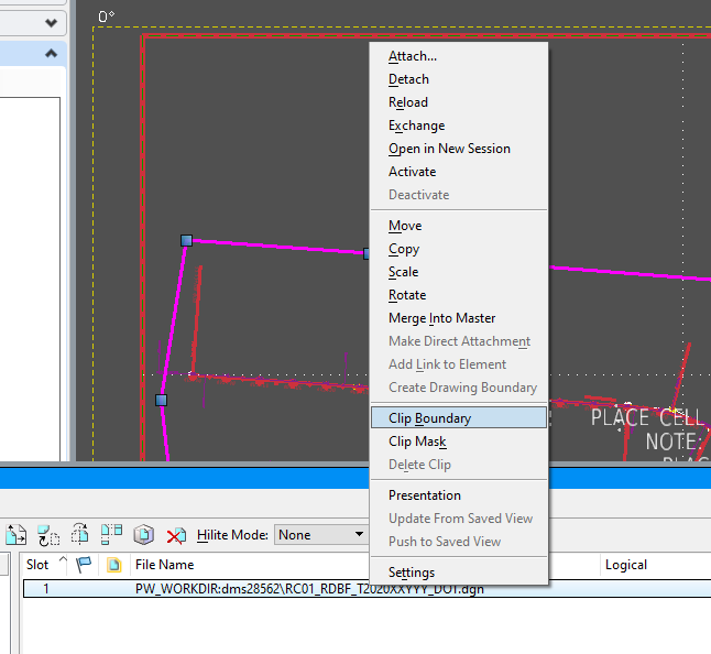
3.2.14. Go to your Reference dialog, right-click on the appropriate reference(s) and select Clip Boundary. Select the closed shape you created. ! This ties your clip boundary to this shape. If you need to change the clipped boundary, just modify this closed shape. Note, this should not print per DelDOT CADD Standards.
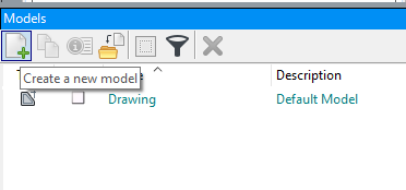
3.2.15. In the Models Dialog, Create a new model.
3.2.16. Type: Set to Sheet From Seed.
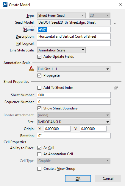
3.2.17. Seed Model: Browse to 02 Standards > Seed_Files and select the appropriate seed.
3.2.18. Name: Set the name of the sheet.
3.2.19. Fill out the remaining fields as necessary and hit OK.
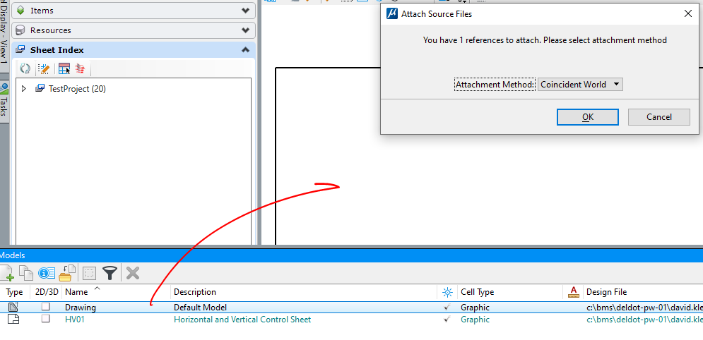
3.2.20. Open the Models dialog, drag and drop the Drawing model into the sheet model and choose Coincident World.
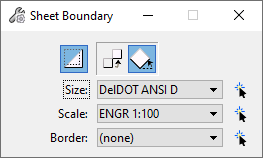
3.2.21. Right-click and hold in white space and select Sheet Boundary.
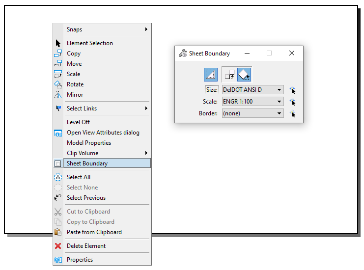
3.2.22. Set Scale appropriately.
3.2.23. Confirm that Move is selected. Tentative to the lower left corner of the Sheet Boundary and move to the corresponding point on your Sheet Border.
3.2.24. Repeat step 3.2.21 this time selecting Rotate and rotate as necessary.
3.2.25. Add common cells to the Sheet Model as necessary (ie SB_B2x, SB_B1, SB_B4, etc…).
3.2.26. Add sheet to Sheet Index. See section 2.5 for more details.
3.2.27. Close MSCE and check in all files.
3.3. Create non-georeferenced Secondary Sheets (TS, DT, etc…).
3.3.1. Follow 3.2.1 through 3.2.4 choosing a Sheet seed instead of a Drawing seed. ! This is starting to feel like a Choose-your-own-Adventure! Exciting!
Please familiarize yourself with section 3.2 as it goes into more detail.
3.3.2. Open the Reference Dialog and attach your Sheet Border file.
3.3.3. Attach any additional reference files as necessary.
3.3.4. Set your scale as necessary. See step 3.2.8.
3.3.5. Add common cells to the Sheet Model as necessary (ie SB_B2, SB_B1, SB_B4, etc…).
3.3.6. Add sheet to Sheet Index. See section 2.5 for more details.
3.3.7. It is recommended that all work be done in a Design or Drawing model and referenced into the Sheet Model. Please see Advanced Discussion 4.2 for more details.
3.3.8. Close MSCE and check in all files.
4. Creating Renditions
Renditions are how you plot inside of ProjectWise, which uses iPlot behind the scenes.
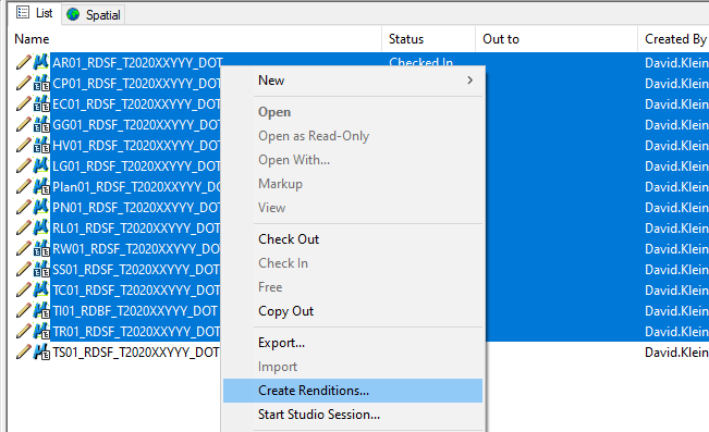
4.1. In PW, select files to be printed, right-click and select Create Renditions...
4.1.1. Change any options from their default values as necessary. Make note of the folder listed at the bottom, as this is where the prints will be sent.
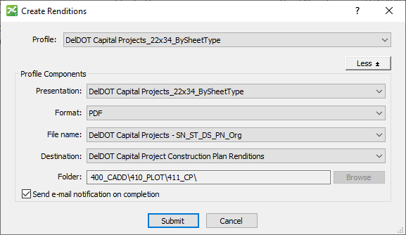
It is recommended that you have Send e-mail notification on completion checked.
4.1.2. Once the job is complete the prints will show up in the appropriate _PLOT folder as individual PDFs. Combine them as necessary. ! Note, if you do not see numbers before each PDF, this probably means you did not enter them into the Sheet Index.
4.2. Combine Multiple files into a single PDF.
The following section will detail the preferred method for combining multiple PDFs into a single PDF using Bluebeam. You will need Bluebeam, ProjectWise Explorer Client and Connection Client installed on your machine. You will also need to be signed into Connection Client.
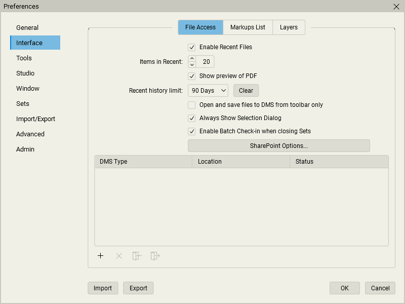
4.2.1. Load Bluebeam, go to Revu > Preferences > Interface > File Access. Make sure the options shown below are checked. Click the “+” icon.
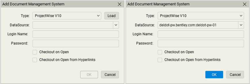
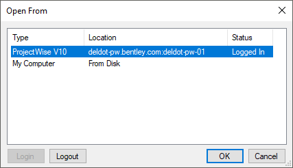
4.2.2. Under Type select ProjectWise V10, hit Load and then OK.
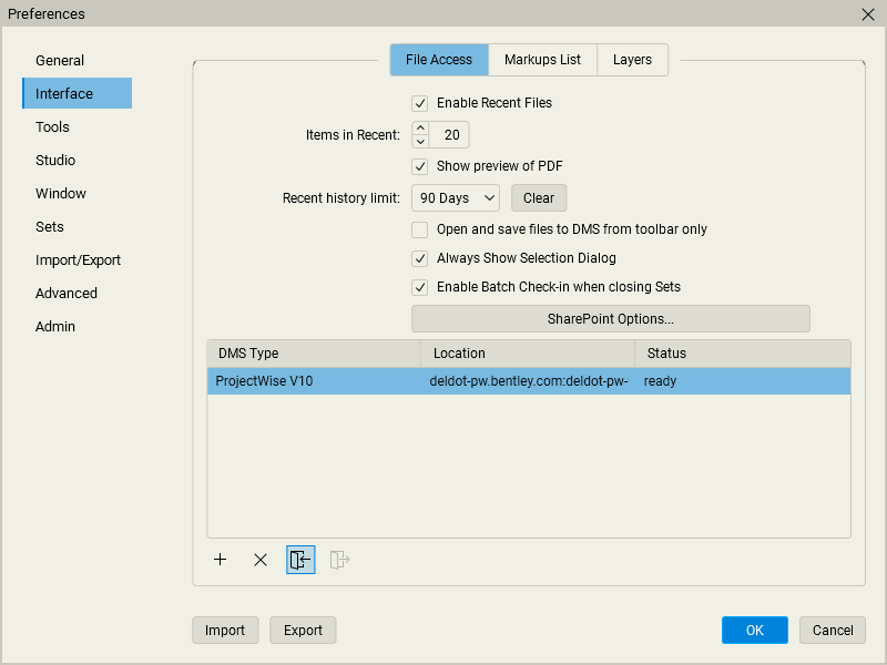
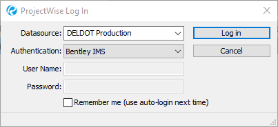
4.2.3. Select the ProjectWise v10 line and click the Sign In button.
4.2.4. Confirm the following Settings and click Log in.
4.2.5. Click OK to close the Preferences Dialog.
Note, selecting File Open will now give you the option to determine which data source to choose from.
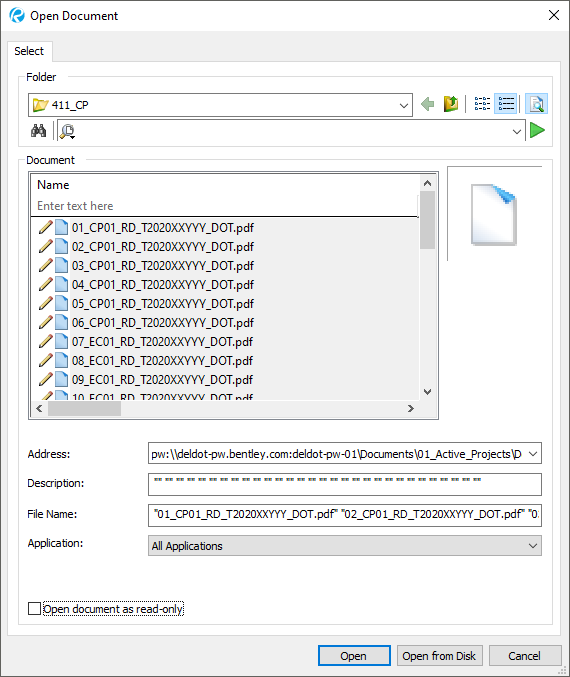
4.2.6. File > Create > From Multiple Files and select the ProjectWise datasource.
4.2.7. Select the appropriate files and hit Open.
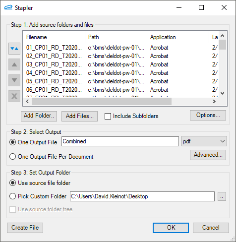
4.2.8. In the Stapler Dialog, under Step 2: Select Output, select One Output File and enter a name.
4.2.9. Under Step 3: Set Output Folder, select Use source file folder and select Create File. ! Alternative: You can save to your Desktop and then close the document after step 4.2.10. Drag the file from your Desktop and drop into PW using No Wizard.
4.2.10. Right-click on the tab of the newly file created, select Save-As… and choose the ProjectWise datasource and hit OK.
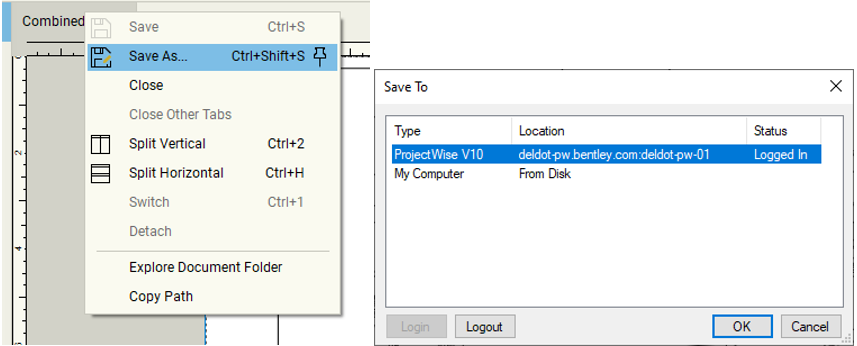
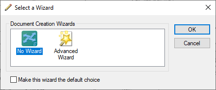
4.2.11. Choose No Wizard and hit OK.
4.2.12. In the Save Document As dialog, hit the Select button and navigate to the appropriate folder and hit OK.
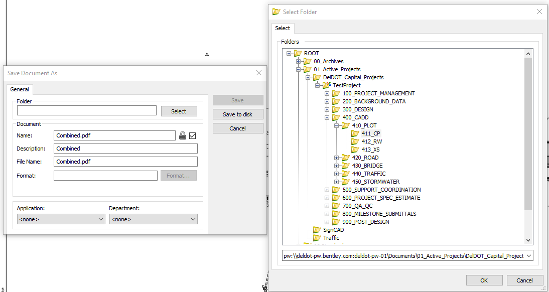
4.2.13. Click Save.
4.2.14. The file is now inside of PW and BB has it Checked Out. Click the DMS icon on the file tab and select Check In.
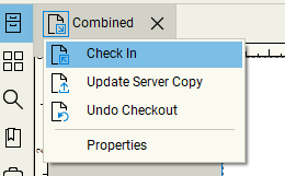
4.2.15. The DMS icon will change to a Lock. You can now close the file.
5. Advanced Discussions
This section will cover topics that supplement the above process or provide alternative methods. This section will rely heavily on the previous sections and cover in less explicit detail. It is recommended that you go through the other sections first as they will be referenced for additional detail.
5.1. Working with Distributed Designs.
This following section will cover an alternative method to section 2 for setting up Primary Sheets using multiple Reference Composite DGNs, one for each Primary Sheet type (ie SS, GG, CP, etc). This offers greater flexibility with the plotting system and facilities multiple designers working concurrently on a project at the expense of more time and effort to setup and manage files.
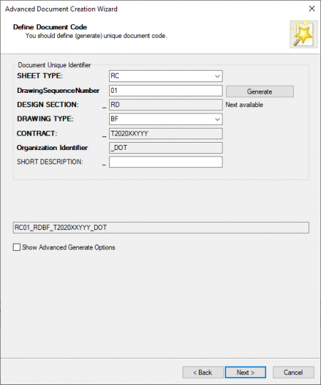
5.1.1. Following section 1.3, create multiple RC files, one for each Primary Sheet type using the SHORT DESCRIPTION to differentiate. The following will provide an example for Signing and Striping.
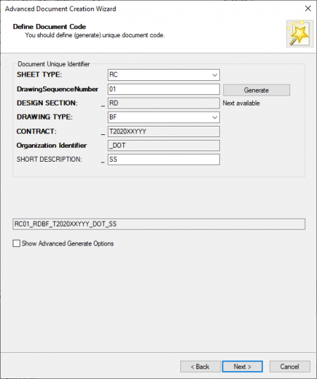
5.1.1.1. Set SHEET TYPE to RC.
5.1.1.2. Set DRAWING TYPE to BF.
5.1.1.3. Set SHORT DESCRIPTION to SS.
5.1.1.4. Click the Generate button.
It is recommended to click the Generate button last, as the number generated is dependent on the full file name. This will mean you will have multiple files starting with RC01:
RC01_RDBF_T123456789_DOT_SS
RC01_RDBF_T123456789_DOT_GG
RC01_RDBF_T123456789_DOT_CP
If you would prefer to have them sequential, click the Generate button before entering the Short Description:
RC01_RDBF_T123456789_DOT_SS
RC02_RDBF_T123456789_DOT_GG
RC03_RDBF_T123456789_DOT_CP
5.1.2. Following section 1.5, on step 1.5.3, make sure to set New Level Display appropriately. This setting controls the behavior of levels used in a reference after the file is attached.
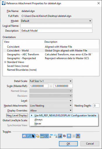
MS_REF_NEWLEVELDISPLAY - If set, MicroStation displays newly created levels in references. By default, when new levels are created in a model that is referenced by another model, the new levels are not displayed when the referencing model is opened. Newly created models are considered until "Save settings" is performed. This functionality only works when both the master file and referenced files are in the V8 file format.
- Use MS_REF_NEWLEVELDISPLAY Configuration Variable
This uses the value set by the CADD standards. The CADD standards currently have this set to Always.
- Always
New levels will always be turned on.
- Never
New levels will always be turned off.
5.1.3. It is recommended to set the RENDITION SET FILE to DEFAULT in the properties for the Sheet File. This will bypass the level display set by the SET files and allow you to manually control level on/off. In each Reference Composition file, you will need to set the level display for that file and save settings.
5.1.4. Following section 2.1, when setting up the Primary Sheets, each set will need to be setup from its corresponding Reference Composition. For example, when setting up the Signing and Striping Sheets, it will need to be done from the Signing and Striping RC file.
5.2. Design vs Drawing vs Sheet Models.
MicroStation DGNs are made up internally with Models, which are organized into three types: Design, Drawing and Sheet. The Department will be utilizing all three model types per Bentleys Documentation.
Please note that View Groups are not the same as Models. When switching back and forth between Models, it is recommended to use the Models Dialog.
From Bentleys documentation site (docs.bentley.com):
Models
When you first create a new DGN file from one of the seed files, this provides the empty container setup with a default model ready for you to create your design. If you use a 2D seed file, then the default setup is 2D, while a 3D seed file defaults to a 3D setup. In either case, you can create both 2D and 3D models in the open DGN file. Every model has its own set of eight views. The model whose views are displayed or available for display at a given time is the active model. You can create three types of models — design, sheet, and drawing.
* Design model — consists of design geometry and can be either 2D or 3D. A design model can also be used as a reference or placed as a cell. By default, the view windows of a design model have black backgrounds.
* Sheet model — a type of model that serves as an electronic drawing sheet. It typically consists of design model references that are scaled and positioned to create a printable drawing. By default, the view windows of a sheet model have white backgrounds.
* Drawing Model — a subset of a 2D or 3D design model, used to apply annotations, dimensions, callouts, and other embellishments to a design. By default, the view windows of a drawing model have gray backgrounds.
Every model has its own unit system. Conversely, levels are DGN file-specific and not model-specific. Using the Models dialog , you can create and switch quickly between models in a DGN file.
Alternatively, you can use the View Groups window to rapidly switch between models visited in the current design session. These can include models in other DGN files.A simple Google search can turn up multiple documents on the topic for further reading.
5.3. Removing Named Boundaries and Boundary Groups.
The following section show how to delete Named Boundaries and Boundary Groups.
5.3.1. In the Drawing Production tab, select the Named Boundaries manager.
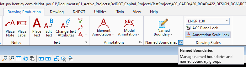
5.3.2. The Named Boundaries manager will show you all Boundary Groups in the current file.
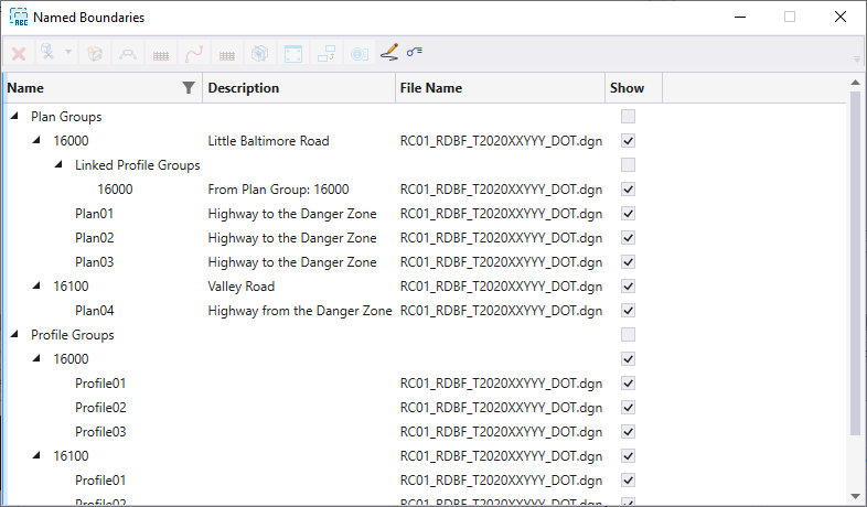
5.3.3. Select a group or individual boundary. Right-click and select Delete or click the red X in the upper left corner of the manager.
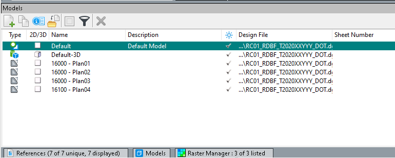
5.3.4. After Deleting a Boundary or Group of Boundaries, it is recommended that you also go to the Models Dialog and Delete the associated models.
5.4. Creating special sheet types
This section will cover creation of specific sheet types not explicitly covered under Primary Sheets and Secondary Sheets.
5.4.1. Profiles
***WARNING*** - An issue has been identified with ProjectWise and profiles that have been sheeted in files separated from the Design and Drawing models. Please refer to these instructions at this time for this section.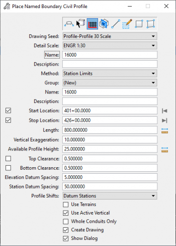
5.4.1.1 In PW, create PF01 in your DESIGN_DGN folder as a Base File. Set to open with ORD.
Ex. In folder 422 > PF01_RDBF_T2020XXYYY_DOT
5.4.1.2 Open the file in ORD and reference in your RC.
5.4.1.3 Open a Profile Model for the desired Alignment.
Note, if you receive the following error: “You cannot open a profile view from another file”.
The most common cause of this is that you have not created a profile for that alignment in the main file.
5.4.1.3.1. Open the file that houses the Alignment (typically the AL Strip Reference file).
5.4.1.3.2. Select the Alignment in question, right click and hold, and select Open Profile Model.
Note, this triggers ORD to create the Profile Model behind the scenes.
5.4.1.3.3. Save, close and check the file back into PW.
5.4.1.3.4. You should now be able to open profile view in the reference.
5.4.1.4 Open Place Named Boundary Dialog.
5.4.1.5 Set mode to Civil Profile.
5.4.1.6 Set Drawing Seed.
Profile Only 30 Scale creates one Profile Boundary per sheet.
Profile-Profile 30 Scale creates two profiles Boundaries per sheet.
5.4.1.7 Fill out Names and Descriptions as necessary.
5.4.1.8 Enter Start Location and Stop Location.
Note, this will be the Start and Stop of the range for which you want to create sheets.
5.4.1.9 Make sure Create Drawing and Show Dialog is checked.
5.4.1.10 The profile model view will show where the Named Boundaries will be placed. Data to accept.
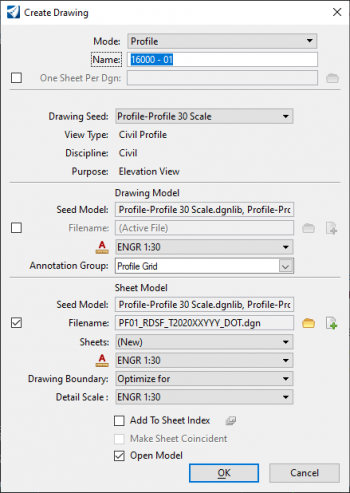
5.4.1.11 In the Create Drawing Dialog, change options from defaults as needed.
5.4.1.12 Under the Sheet Model section, Check the box next to Filename.
5.4.1.13 The first time you do this, click the Create New Sheet File button, and create PF01 as a Sheet File and place in your SHEET_DGN folder.
5.4.1.14 The second time you do this, click the Browse Sheet File button, and select the file you created above.
If you chose the Profile-Profile seed option and have only used one of the profile Boundaries, you can utilize the second one by selecting the appropriate Sheet via the Sheets dropdown, and then selecting the appropriate Boundary via the Drawing Boundary dropdown.
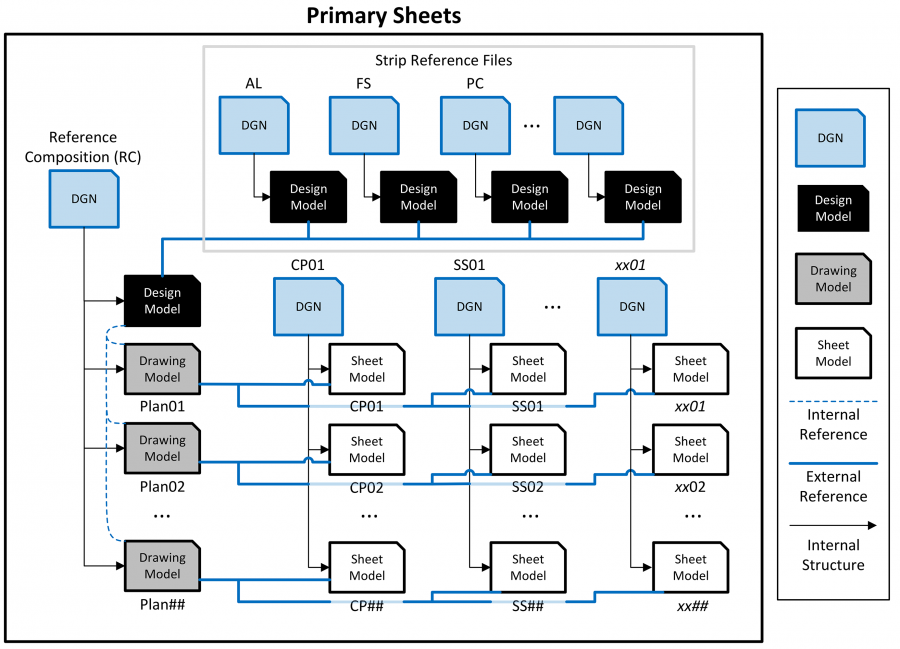
5.5. Diagram: Reference Structure for Primary Sheets.
5.6. Diagram: Reference Structure for Secondary Sheets.